Its about other speeds and needs there, they use it as a shield because they radiate pulses. Yours worked well enough so no worries. When a Kelvin sense wide band supply is sticking next to the phono in a combo pcb we better define the gnd return nodes IMO. I will fully test when time comes so to be zero issues anyway. BOM, iron, hook up, music. If not I will scrap it back to square 1.Dont know anything about pcb design, but reason i chose ground plane was strong adherance of DAC folks. They seem religious about those things in their loe noise, low distortion world..
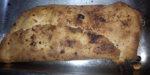
You run strong bias. I see it charred at the edges. Turn your B+ down a bit and center at test point better next time.😛
News....
After long periods of listening and many builds I am inclined to state second stage miller is 1.03nF for the folded.
After long periods of listening and many builds I am inclined to state second stage miller is 1.03nF for the folded.
Quite similar.... in fact I use always the same value as a ballpark.... tunning by ear is needed in the end.
Quite similar.... in fact I use always the same value as a ballpark.... tunning by ear is needed in the end.
Tuning the RIAA components by ear, RCruz? 😕
So it sounds right to you .. or so you get the RIAA response curve to within, say, 0.2dB?
BTW, there are several well-reagrded phono stages - like the Allnics - which state a +/-0.5dB for their RIAA response.
Regards,
Andy
Hi Andy
If you follow the exact values indicated by Salas in his schematics, you do not need to tune by ear but, if you can not get the exact values, as it happens to me seldom, there is a need to tune the high freq cap (15nF) by listening.... I gather two or three different systems and listen to the builds... Then I collect info from the various listeners and trim this cap acordingly.... that is what I do.... But if you want to be technical, get a signal generator, an anti riaa circuit, a scope... and measure things.
If you follow the exact values indicated by Salas in his schematics, you do not need to tune by ear but, if you can not get the exact values, as it happens to me seldom, there is a need to tune the high freq cap (15nF) by listening.... I gather two or three different systems and listen to the builds... Then I collect info from the various listeners and trim this cap acordingly.... that is what I do.... But if you want to be technical, get a signal generator, an anti riaa circuit, a scope... and measure things.
Hi SalasUse BF245A in Vref or 2SK117GR, catches up faster.
Forgot to ask... why do these fets catch up faster ?
Can I use a very low Idss K170 instead ?
(I believe I found the issue... the vref trimmer is drifting and needs replacement... that is why it sometimes does not work)
I found higher Vgs in my latest batch of BF245A the other day so rule it out, stick to K117GR as an alternative. Its the different tempco curves in various types that make them behave differently for drift under certain VDS and current bias.
Hi RC
What do you think it is for the regular Simplistic ?
Any idea peoples ?
Cheers
Si.
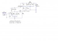
The MM is less gain, less second stage Miller. Different Rs change that also due to different degeneration. The given circuits are measured to be OK. From there people can slightly tune to preference or not.
Salas I've just seen the preliminary pcb design (post #9651)
Nice idea! A bit too compressed for my taste (I'd rather use 1/2W resistors), but interesting indeed. (As you might know I'm presently making my own with SSLV1.2R on board)
I noticed that the cascoding bjt might be different: two dissimilar pin out. Are you going to replace the 560C or offering a second option for that?
- Home
- Source & Line
- Analogue Source
- Simplistic NJFET RIAA