Yes, at the monastiraki end of Athinas.
4 shunts (1 for each stage) should be the optimum then. Have you tried it like this ? Did you hear differences ?
4 shunts (1 for each stage) should be the optimum then. Have you tried it like this ? Did you hear differences ?
With two shunts (one per channel) there was a small difference. With four and per stage, I don't know. But I prefer to bet on the per stage approach.
4 complete shunts from a dual sec pw xfrm? Raw p.s. (bridge & caps) shared by two shunts?
Or maybe dual sec - 2 raw p.s. - 2 CCS stages followed by 4 shunt stages? (poor isolation between the two shunts feeded by a single CCS, I guess)
I'm very interested on these arrangements.
Or maybe dual sec - 2 raw p.s. - 2 CCS stages followed by 4 shunt stages? (poor isolation between the two shunts feeded by a single CCS, I guess)
I'm very interested on these arrangements.
insert a small resistor to feed each shunt from the common CCS.
resistor value selected to drop ~1V
resistor value selected to drop ~1V
Hi,
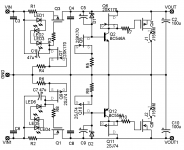
Q5 needs to be a low Vds device. Keep the sk170 here.
Q6 & Q7 do not need low Vds devices in these locations. Save your expensive and soon to be obsolete 2sk170 for where they are needed.
Replace Q6 & Q7 with cheap and easy to obtain jFETs.
Replace all the 2sk74 with Nchannel devices.
Q5 needs to be a low Vds device. Keep the sk170 here.
Q6 & Q7 do not need low Vds devices in these locations. Save your expensive and soon to be obsolete 2sk170 for where they are needed.
Replace Q6 & Q7 with cheap and easy to obtain jFETs.
Replace all the 2sk74 with Nchannel devices.
*If there is need to economize on Toshiba devices.
Has been done with 2Nxxxx devices except Q5 when there was a shortage. Link. Worked OK. Neg schema. Drains towards earth.
Has been done with 2Nxxxx devices except Q5 when there was a shortage. Link. Worked OK. Neg schema. Drains towards earth.
Hi salas,
I'm making up my BOM and I would appreciate your suggestions on riaa components.
Reading the thread once more I think that best results come from:
R3 - shinkoh
R4 - ?
C3 - SSG
C2 - ?
Are the drain resistors (R1,R10) important sound wise, and if they are, what are you suggesting ?
I'm making up my BOM and I would appreciate your suggestions on riaa components.
Reading the thread once more I think that best results come from:
R3 - shinkoh
R4 - ?
C3 - SSG
C2 - ?
Are the drain resistors (R1,R10) important sound wise, and if they are, what are you suggesting ?
Rload & R3 & R4 Shinkoh. All others Takman or Kiwame.
C3 Silver Mica CCCP C2 33n MKP // Silver Mica. C4 Teflon FT-3 CCCP.
Rload are 3rd in importance after CartLoad and R3, and the source degenerators. You will normally not need any Cx. What is your cart?
C3 Silver Mica CCCP C2 33n MKP // Silver Mica. C4 Teflon FT-3 CCCP.
Rload are 3rd in importance after CartLoad and R3, and the source degenerators. You will normally not need any Cx. What is your cart?
A Yamaha MC2 (a poor man's Koetsu at its time).
If exact value for C3 is not available are you opting for nearest smaller or bigger value ? Any more specific suugestion for the MKP part of C2 ?
The type of Silver MIca is SSG or any type will do ?
If exact value for C3 is not available are you opting for nearest smaller or bigger value ? Any more specific suugestion for the MKP part of C2 ?
The type of Silver MIca is SSG or any type will do ?
C3 is the most important value for tone. Guys buy from ebay the large metal canned Soviet Silver Mica at about 15700pF and shunt it with a 300pF Soviet SM. Best Value best sound.
For the C2's MKP part Siemens worked OK, but the SMs upon it rule the tone.
You will need to measure and match the values.
Prefer SSG, value for money, and not the typical metal sheen tone of modern SM.
For the C2's MKP part Siemens worked OK, but the SMs upon it rule the tone.
You will need to measure and match the values.
Prefer SSG, value for money, and not the typical metal sheen tone of modern SM.
Attachments
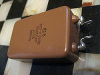
The blue brick ones ?Salas said:For the C2's MKP part Siemens worked OK, but the SMs upon it rule the tone.
Last question for tonight.
What is the suggested current per shunt
- for 2 shunts (1 per stage, per channel, as we discussed earlier)
- for 4 shunts (1 per stage )
What are the corresponding values of R1 for the above. Are there any other changes that should be made ?
Thank you salas. I won't torture you more. At least for tonight..
Yes the blue ones. But in general don't worry much about the MKP base. Its the SM bypass that matters.
For any shunt configuration or number of pieces, use R1=10R and 1.8V LEDs. That will give about 150mA. Of course you could go very low if you want to avoid sinks, like using 33R for about 60mA for each shunt, its that it sounds dynamically a bit better at 150.
For any shunt configuration or number of pieces, use R1=10R and 1.8V LEDs. That will give about 150mA. Of course you could go very low if you want to avoid sinks, like using 33R for about 60mA for each shunt, its that it sounds dynamically a bit better at 150.
I could never imagine how time consuming is to select leds..
Salas I suspect that specifing 1.8 V Leds instead of 1.7V is because V varies with current (specs are usally at 20ma and we are loading leds with 8-10 ma). Another thing that I realized (please correct me if wrong) is that our needs rule out low current leds and super bright 5mm ones are usally near spec.
Beeing on the subject have you read this thread ?
Yes I am aware of those measurements I have brought it up in the simplistic regulator thread in its start when talking about Zeners.
Remember that the total Vdrop in the LED string is what we look for. So you can mix and match different Vf LEDs. Green ones are steadier near their average, yellow next steadier, red less steady in my stash for instance. I mix colors some times and I get the total Vf. My DVM measures it directly so I don't have to use a battery and a resistor, so that helps. 1.8V is what I got as mean average from off the shelf generic green LEDs. Yes, about 10mA is what I target. So size your test resistor (if you measure them on some psu voltage using a resistor) for about such a current. Say you have a 9V battery cell, and your LEDs are about 2V and under, then 9-2V=7V/R=ILed.
Any Vf total between 7-8V will do for the phono cascode input stage. Just match the LED strings total voltage drop between channels.
- Home
- Source & Line
- Analogue Source
- Simplistic NJFET RIAA