No, You still will have Q2 connected to gnd
try to simulate and then You can have a try in real
any kind of termination will change the low end
You can choose a higher impedance riaa net
components also, to be less affective on Rload of Q1.
try to simulate and then You can have a try in real
any kind of termination will change the low end
You can choose a higher impedance riaa net
components also, to be less affective on Rload of Q1.
The first stage on my schematic has 11k Zout (Ro=Rriaa(V1GOhmload-VoRIAAload)/Vo. If I go 50xtimes that for series RIAA resistor, then the RIAA capacitors will be fictionally small and bad for tolerances or quality dielectric availability. If the Zout is embedded in the RIAA, where is the difficulty? Q2 with 2.2Meg input is 50x the 47k combined driving impedance. Will it get seriously loaded?
P.S. Which schematic is your tube RIAA? Can you post it? So I can see why you had to do those mods. If its not proprietary of course.
P.S. Which schematic is your tube RIAA? Can you post it? So I can see why you had to do those mods. If its not proprietary of course.
dual mono design ?
As not more of 30db separation , worth to upgrade ?
no 1k but not differ too much from 3k , lowering the load close the sound , as modern hi gain mc work with standard 47k
As not more of 30db separation , worth to upgrade ?
no 1k but not differ too much from 3k , lowering the load close the sound , as modern hi gain mc work with standard 47k
Don't know for double mono, it seems unworthy the way you put it. Maybe side benefits from using 2 power supplies. No cross of GNDs etc.
The Denon has 160 Ohm Zout, so 1.5k upwards is fully testable for system tonal matching.
The Denon has 160 Ohm Zout, so 1.5k upwards is fully testable for system tonal matching.
Kevin posted triodeguy's (John Sears) RIAA -- I tweaked it a bit with my "LaPlace-i-nator". The 2N3819 is a fraction of the cost of a 2SK170, I haven't measured the noise, however.
An externally hosted image should be here but it was not working when we last tested it.
jackinnj said:Kevin posted triodeguy's (John Sears) RIAA -- I tweaked it a bit with my "LaPlace-i-nator". The 2N3819 is a fraction of the cost of a 2SK170, I haven't measured the noise, however.
An externally hosted image should be here but it was not working when we last tested it.
Richard Sears.... Otherwise cool work..
IMO The 2N3819 might prove to be just a bit noisy in this application.
Zoran said:This is good concept...
..
Use passive inverse riaa network for simulation
not only straght signal...
try haggerman inverse riaa
cheers
You will be amazed
Hi Zoran. Did the Bode plot driven from Hagerman inverse. I added the ''lost constant'' too.😀
Well it looks doable, wasn't off. I also sized the source resistors bypass capacitors more generously for better low bass phase shift. I will use 500R trimmers there. That and matched 2SK170BLs should do the channel matching trick.
Hope that it will remotely resemble the gain and time constants in real life test!

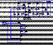
Attachments
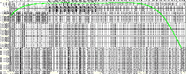
P.S. The plot above appeared as a joke when uploaded. 
Info on its scaling:
It has 10Hz to 100kHz limits, its 20Hz and 20khz are -0.4dB. Its octave spaced per main lines horizontally and 0.1dB per vertical dent.
And the ''promissing'' circuit. Shown driven from a Hagerman inverse RIAA with 60dB attenuation of input generator.
Info on its scaling:
It has 10Hz to 100kHz limits, its 20Hz and 20khz are -0.4dB. Its octave spaced per main lines horizontally and 0.1dB per vertical dent.
And the ''promissing'' circuit. Shown driven from a Hagerman inverse RIAA with 60dB attenuation of input generator.
Attachments

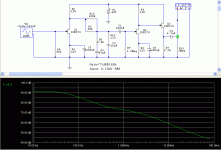
It seems to be good?
pretty flat
I saw that You are used inverse Hagg. cir for sim.
(1.91K on gif...)
*
add Cable capacitance at the input,
and output and input resistor of the next stage on out...
cheers
*
pretty flat
I saw that You are used inverse Hagg. cir for sim.
(1.91K on gif...)
*
add Cable capacitance at the input,
and output and input resistor of the next stage on out...
cheers
*
use real value of output not 1Meg but 10K
with Ccable of 100-150p
input is 47K not 560 ohms
or 100 for MC
also 100-150pF of Cable
(10uF Cout)
with Ccable of 100-150p
input is 47K not 560 ohms
or 100 for MC
also 100-150pF of Cable
(10uF Cout)
I would terminate with 560R to 1K2 if I had a 60R Zo cartridge. The Hagerman assumes 60R Zo. That is arbitrary. We are free to choose how to terminate any given cartridge. I can load it down with 100R and sim for less effective input voltage (the 0.25mV will halve with 60R Zo on 100R load) and 150pF input cable parasitic. The output I have tested low before, I have a buffer for that, no worries. The 1 Meg is there to get shunted by loads, but to keep the output cap static happy when not.
Anyway, here it is as you wanted to see it. Still solid. 🙂 ...In theory.😎
*For anybody who might be attempting this before I get a chance, be sure to remember that the gain is based on 10-12mA Idss 2SK170BL @ 9V
Anyway, here it is as you wanted to see it. Still solid. 🙂 ...In theory.😎
*For anybody who might be attempting this before I get a chance, be sure to remember that the gain is based on 10-12mA Idss 2SK170BL @ 9V
Attachments
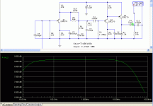
Try adjusting the value of R17 -- or eliminating it -- I am getting quite different results in the Salas RIAA than you are deriving.
Different software, and models probably. Show your best Bode and RIAA values. In case it deviates in practice we should be having a plan B.😉
jackinnj said:Try adjusting the value of R17 -- or eliminating it -- I am getting quite different results in the Salas RIAA than you are deriving.
R17 eliminated...
Attachments

salas said:Different software, and models probably. Show your best Bode and RIAA values. In case it deviates in practice we should be having a plan B.😉
I use LaPlace transform with values of 3180, 318 and 75uS -- Walt Jung shows how to do this in his text "Op Amp Handbook". What I saw with R17 was a pretty serious peaking in the ultrasonic region. If you hunt around on the ADI website you can find that chapters of the book are archived.
Dennis Colin in his article "Tweaking the Passive Inverse RIAA Network" assumes the 3.18 uS compensation (Audio Xpress August 2007, a PDF can be found on the AX website http://www.audioxpress.com/magsdirx/ax/addenda/media/colin2808.pdf --
You might want to adjust the values of the Inverse RIAA net you are using, Denis has them acurate for a micro-deci-Bel ! But regardless, the values are going to be different than those derived using the LaPlace transform.
So it will be better off without R17 and it will be OK in general, according to your simulations? How high did you get the peaking? Miller does not allow very high with this open loop circuit.
LaPlace --
For the enhanced RIAA include in the numerator 3.18 uS
.PARAM T1 = {3180}
.PARAM T2 = {318}
.PARAM T3 = {75}
.PARAM T4 = {3.18} ;Reference Enhanced RIAA Constant
ERIAA 5 0 LAPLACE {ENORM*V(1)}={((1+(T2*1E-6)*S)*(1+T4*1E-6)*S)))/((1+(T1*1E-6)*S)*(1+(T3*1E-6)*S))}
Edit -- there appears to be one wrong number in Table 1 of the article.
- Home
- Source & Line
- Analogue Source
- Simplistic NJFET RIAA