2SK367BL Spread - which ones for Q1 & Q2
Hi,
I bought 10 2SK369BLs and I measured the IDSS as below:
9.110
9.106
9.000
9.026
9.016
9.078
15.143
13.134
11.056
12.610
The recommendation for Q1 and Q2 is in the 11-13 mA range but as you see the matching is much better around 9.xxx.
What are the recommendations please?
Barry
Hi,
I bought 10 2SK369BLs and I measured the IDSS as below:
9.110
9.106
9.000
9.026
9.016
9.078
15.143
13.134
11.056
12.610
The recommendation for Q1 and Q2 is in the 11-13 mA range but as you see the matching is much better around 9.xxx.
What are the recommendations please?
Barry
well wishes
Cheers guys.
I am trying to build it slowly and carefully....... for once.
I will let you knee how it goes.
Barry
Cheers guys.
I am trying to build it slowly and carefully....... for once.
I will let you knee how it goes.
Barry

Lol. Sounds like he is trying to break the sound barrier in a bucket. Good luck building, dont fake it. It sounds f**ing great, not the best but awesome.
what i did
hi, it's my first post here, after many hours anonymus reading 😀
this is what i finally did with components i had...
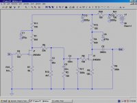
the gain is a bit higher for MM but a bit... and sounds incredible. spent last 5 hours listening, after four sides i added 56p at input, is better now. there is realy gentle hum from naked design, but as soon as i have enough time it will go in a metal box. PSU is 63V from an old project with C-L-C filter, after that r-c-r-c to go down to about 40V, temporary, for a test. differences between two stages are due to different idss of fets, matched in couples for first and second stage. result is 15.1V on 3 of drains, and 15.0 on last.
all fets are 2sk170bl.
great work mr.Salas
hi, it's my first post here, after many hours anonymus reading 😀
this is what i finally did with components i had...
the gain is a bit higher for MM but a bit... and sounds incredible. spent last 5 hours listening, after four sides i added 56p at input, is better now. there is realy gentle hum from naked design, but as soon as i have enough time it will go in a metal box. PSU is 63V from an old project with C-L-C filter, after that r-c-r-c to go down to about 40V, temporary, for a test. differences between two stages are due to different idss of fets, matched in couples for first and second stage. result is 15.1V on 3 of drains, and 15.0 on last.
all fets are 2sk170bl.
great work mr.Salas
Attachments
Thanks guys
Barry
Barry what is your cartridge? How much gain are you looking for? That kind of determines which and how many 2SK369s you need. I assume low output MC, as I think did others here who suggested particular pairs.
hi, it's my first post here, after many hours anonymus reading 😀
this is what i finally did with components i had...
the gain is a bit higher for MM but a bit... and sounds incredible. spent last 5 hours listening, after four sides i added 56p at input, is better now. there is realy gentle hum from naked design, but as soon as i have enough time it will go in a metal box. PSU is 63V from an old project with C-L-C filter, after that r-c-r-c to go down to about 40V, temporary, for a test. differences between two stages are due to different idss of fets, matched in couples for first and second stage. result is 15.1V on 3 of drains, and 15.0 on last.
all fets are 2sk170bl.
great work mr.Salas
Welcome to the forums. Nice to build the basic initial architecture with what parts, idss, and psu you have got. Surely you don't need a buffer stage but you need the gate resistors? Some buzz maybe comes from the rail too. Such stages have almost no PSRR. Someday if with MC cart make the FSP (find & save four matched K369BL from now).
I found the problem!!!
I connected scope to the first point -> to power rail and bingo, scope got crazy. Huge Hight Frequency noise which disappears in time. It is my new RAW PSU board. So, switched to the old one and no noise at all. Did not figured out what causes such phenomenon to my new PCB. It is simple RCRC+Kmulti circuit, but I'll do later.
The challenge now is to drop V on Raw PSU to acceptable level. I have 51.13/51.76VDC out under load. To add Rdrop prior first C is not that easy in that PCB. Need to cut some traces and ctc. I'll do that tomorrow...
Now you got some good evidence in your hands about the weird warm up noises origin. Better that the anomaly is not in the FSP itself. Scope the compound feedback BJTs pair in Kean's multiplier and ask him for solutions if they oscillate during warm up. Maybe some of your feed/load values upset it. The old raw PSU board is the classic one from the guide?
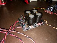
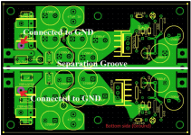
I'm so happy I found the problem. Now, it is not classic from manual. Please see attached pictures. The black assembled one is the new one that give me a trouble. Now, I use similar to one that on the right side with green color and it is optimized for dual +/0.
Based on basic calculation, I need to add 20R for drop to 49VDC.
Vdrop=Rr/Rtotal*Vtotal
20/470*51=2.2V
Based on basic calculation, I need to add 20R for drop to 49VDC.
Vdrop=Rr/Rtotal*Vtotal
20/470*51=2.2V
Attachments
Last edited:
Cabling now...hmm... maybe decoupling revision across Kean's input is needed. Scope is your friend. Experiment or ask Kean.
FSP raw PSU is not the most complicated of circuits. Hardly need a board at all. You can make it a CRC if you need to bring some voltages down. Rectifiers, 4 caps, 2 resistors, bleeders and a ground path.
Last edited:
Is there any advantage in using larger diodes for the bridge rectifier than the specified MUR 120s? I've never used such tiny diodes before. They clearly can cope with the load they're subjected to, but perhaps there are faster/ better options.
Cabling now...hmm... maybe decoupling revision across Kean's input is needed. Scope is your friend. Experiment or ask Kean.
By cabling now you meant that I can use it as is without dropping V below 50V?
Sent from my iPhone using Tapatalk
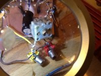
no, i don't need buffer stage, and don't know abouth gate resistors, will try without on next step, no audible hum from rail, with plug disconnected nothing changes in 10-15 seconds running on caps, except slow wolume decrease of cource 😀
today experimented cart loading, 100k trimmers and variable cap from old AM radio, finished at around 85k and 15p, will try few days with 82.5 i have and no caps, sonically there is minor difference with or without 15p, but logic says that this is nonsence with 142-146 L/R wiring and mr. Miller 😉
next step is try trimmers at 150R "missing constant" resistors to see what happpens.
cheers
Attachments
- Home
- Source & Line
- Analogue Source
- Simplistic NJFET RIAA