Very nice build.... where can I find the circuit ?
I guess is attached pic🙂
Attachments
Last edited:
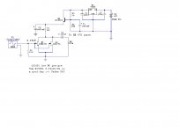
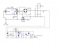
I made BC547C addition to my LM317T PSU with 2 Elna RFS caps, but noise got increased. Please see attached schematics. Did I make mistake somewhere there?
Maybe you kept wrong values for your different voltage. Delete R4 to see (original schematic designation). Move the LED indicator on raw DC input side. Use a 10-20mA bleeder resistor in its place. The 317 needs a certain minimum consumption to wake up.
P.S. I would not use nF range caps across a 317's output. Better a 10-100uF Tantalum or normal ESR lytic.
Attached pics pre-pre
You can use that for the Itch also Merlin. VS SUT. Although people usually don't mix semis and valves tone, they prefer their vanilla and chocolate separate.🙂
Maybe you kept wrong values for your different voltage. Delete R4 to see (original schematic designation). Move the LED indicator on raw DC input side. Use a 10-20mA bleeder resistor in its place. The 317 needs a certain minimum consumption to wake up.
P.S. I would not use nF range caps across a 317's output. Better a 10-100uF Tantalum or normal ESR lytic.
Thank you for advise. I'll try and let you know.
It worked!!!!
It is quiet now and also I can hear differences between batteries and that circuit. It has better resolution.
Did not get your coment about caps...
I use 470uF Nichicon KZ and 0.1uf Wima MKP2 on regulator input, and in output I use 0.1uF Wima MKP2 with 10uF Wima MKP2 (10x1uF). Adj also set with 10uF Wima MKP2 (10x1uF).
Please let me know if you see any issue with that arrangement? I corrected drawing and attached it.
Thank you.
Attachments
Congrats. There is no issue per se. Reading about optimizing the 317 passive parts assortment you can google about and try or not. Given there is the extra filter there now imposing its own final characteristics it may prove a useless exercise anyway.
Congrats. There is no issue per se. Reading about optimizing the 317 passive parts assortment you can google about and try or not. Given there is the extra filter there now imposing its own final characteristics it may prove a useless exercise anyway.
Hi Salas,
Thank you again. I was very-very-very helpful.
😀
You can use that for the Itch also Merlin. VS SUT. Although people usually don't mix semis and valves tone, they prefer their vanilla and chocolate separate.🙂
Now I have enough gain with the SUT I prefer all chocolate😉
I'm tempted to mod your 20dB pre-pre to 28dB attached schematic.
Attachments
Maybe that is where we should use the kmultiplier.....
Ricardo, sorry for OT. What are the loading values that you use for the Benz cart?
Maybe that is where we should use the kmultiplier.....
I think it should be used near the DC inputs after the umbilical or somewhere along its way than locally in the raw PSU as you did. As I had recommended initially. There it could filter more EMI/RFI stuff that comes along to the regulators.
I think it should be used near the DC inputs after the umbilical or somewhere along its way than locally in the raw PSU as you did. As I had recommended initially. There it could filter more EMI/RFI stuff that comes along to the regulators.
Indeed, it works much better placed after the smoothing caps and away from the psu 🙂
Ricardo, sorry for OT. What are the loading values that you use for the Benz cart?
Between 2000 and 3000 ohms... system dependent
I rigged up my power supply this morning using an R core transformer with secondaries [18v] connected in series the capacitor with the 2x10k resistors and an led the resultant dcv was 56.4.Is this going to be ok?
Its a Selectronic R core 230VAC.Where I live the mains voltage rarely ever drops below 240v and quite often sits at 245v.I didn't check this morning.
So you use the bleeders too and it behaves too high still. Weird, I use R core too. Even at x1.4 it should hit 50VDC if it was 36VAC. Can you measure the secondary in AC?
Its not that the input sink will not take the 20V drop, its lukewarm with 10V drop, but I am afraid of you frying Q2X in the reg because its going to see VDCin-3LEDS across. Its a 50V spec FET the K117 and it will be right on max VDS edge plus dissipating more. It can be fixed by some resistor in series with the secondary, but better get the 2X15 Selectronic R core when in the UK or Australia it looks like.
Its not that the input sink will not take the 20V drop, its lukewarm with 10V drop, but I am afraid of you frying Q2X in the reg because its going to see VDCin-3LEDS across. Its a 50V spec FET the K117 and it will be right on max VDS edge plus dissipating more. It can be fixed by some resistor in series with the secondary, but better get the 2X15 Selectronic R core when in the UK or Australia it looks like.
I used E-I core transformer :
230V primary
2X36VAC secondary
after plugging the PSU circuit - I am getting ~48VDC for each channel which I guess is fine
-(sqrt2 x 36VAC).
54VDC sounds too much.
230V primary
2X36VAC secondary
after plugging the PSU circuit - I am getting ~48VDC for each channel which I guess is fine
-(sqrt2 x 36VAC).
54VDC sounds too much.
Yours looks normal. That R core surely overshoots spec and gets even higher on UK mains.
P.S. Times 1.33 the measured secondary VAC should be about right for the raw DC expected including losses at the voltage level and VA we use here.
P.S. Times 1.33 the measured secondary VAC should be about right for the raw DC expected including losses at the voltage level and VA we use here.
- Home
- Source & Line
- Analogue Source
- Simplistic NJFET RIAA