Hi, the input cascode voltages are OK from those you measured, but your next stages are squashed for voltages. In all cases we debugged in the course of this thread it was always a matter of wrong connections not following the schematic lines correctly, excess solder making unwanted shorting, rarely a wrong resistor value or a dead fet due to overheating in assembly. Examine thoroughly all of the above. Good news is they all worked in the end bar none.
No need to tell what capacitors for cupling.
Resistors are mostly RC55Y
And 2W Holcos MF with 15ppM
Elitics are new Pana FM type that has beter specs than FT series
More or less sameas Salas SCH he published for me at 24 V suply + the MC prepre.
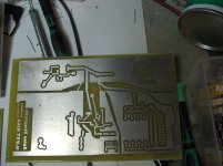
I got the Reflektor board etching away and the second PCB todrill and stuff.
Main thing that realy amzed me ....
It woked straight away
Resistors are mostly RC55Y
And 2W Holcos MF with 15ppM
Elitics are new Pana FM type that has beter specs than FT series
More or less sameas Salas SCH he published for me at 24 V suply + the MC prepre.
I got the Reflektor board etching away and the second PCB todrill and stuff.
Main thing that realy amzed me ....
It woked straight away
Good progress. Lets see if it will pay your efforts back when you will hook it up together with the Reflektors.
Tanks Salas
Realy apreciated
I could have not got there whitout your help
And I am shure it will be realy good.
+ got litle suprise for the Power suply...
Got to get back to work (loads of fun)
So If you do not see me here for a litle while I am heither soldering or rediscovering my record collection.
Just tock this litle break to say
Tanks Again
troubleshoot one channel
I got my salas riaa built but it is not working. I am using the Salas 1.1 bib as the regulator and I am measuring 25.1 volts. I am trying to build the Salas Simplistic NJFET Riaa Version 1.0 PDF(MM or MC High version) not the most current PDF version 11.02.F0
From reading some of the thread there is mention of measuring the drain to ground voltage so I think I measured these correctly.
Q6 - 24.9 volts
Q3 collector - 15.65 volts
Q1 drain - 7.16 volts
Q2 drain - .961 volts
Q5 drain - .443 volts
After rechecking and resoldering q2 and q5 connections
Q2 drain 9.57 volts
Q5 drain 19.6 volts
Still no sound but wanting to know if these voltages are correct?
Thanks
Kerux
troubleshoot one channel - progress
I am finally getting sound out of the one channel. The volume is way too low as I need to go to full volume to hear the music.
I will continue working on it.
Kerux
I am finally getting sound out of the one channel. The volume is way too low as I need to go to full volume to hear the music.
I will continue working on it.
Kerux
troubleshoot one channel -progress - info


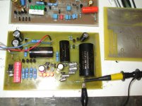
I am attaching some pics of the amp and the one channel.
I am trying to build Salas Version 1.0 MM Version for my Sonographe SG-3 with a Shure M97x cartridge. I have also been using the wiring layouts provided in the 1.0 pdf files.
Thank you for the help.
Kerux
I am attaching some pics of the amp and the one channel.
I am trying to build Salas Version 1.0 MM Version for my Sonographe SG-3 with a Shure M97x cartridge. I have also been using the wiring layouts provided in the 1.0 pdf files.
Thank you for the help.
Kerux
We have got to know what happened. How it came to produce some sound, what changed. So we can follow and make suggestions.
On initial power up and testing, I got no sound. I rechecked my wiring and looked at both the schematic and Ricardo's drawing and saw that I miswired R8 1m. I fixed this and tried again but no sound.
I read some posts where you mentioned measuring the drain to ground voltages so I measured those. You told me that q2 and q5 had problems. So I unsoldered, reconnected and resoldered the connections and then I got the correct voltages. This is my problem on the other channel. I tried the phono amp again and got no sound.
I rewired some of the ground connections, rca jacks and power connections. I reconnected the amp to my stereo and put on led zeppelin 2 and heard sound very faintly if I put my ear next to the speaker. If I turn the volume all the way up, I can hear from a few feet away.
I read some more posts where you mention using a 1k test signal. I am not certain if this and a DMM can help identify the problem. I should add that I used a DMM to test continuity throughout all this.
I think the problem is my soldering skills. This is my first attempt at p2p besides the simple lightspeed. I have only worked with pcbs for the bugle, tubelab simple se and salas bibs previously.
Thanks for your help. The voltage measurements have helped me fix some issues with the other channel quickly.
Kerux
OK. In your shoes I would try the simplest of tests. To attach the DMM on input RCA and read the load resistor for instance. Or on the output and read the output resistor to ground. Else maybe a short in cabling. Another one, can there be a muting to ground along the way by accident? Can there be some wrong resistor value? The fact that you worked some connections and got right voltages, points to practical matters. Review those links against the schematic. Not against some board from the first pdf. Just try to follow the lines with the continuity probing.
Quote from JG at MPP: " They work technically different and they sound different. The transconductance is very fluid and nice and the transimpedance majors on raw dynamics and slam when the cartridge fits, e.g. is of rather low impedance." --- " There is another advantage : the input capacitance of J-Fets is somewhat un-linear and using the sources as input avoids that. It also has more speed theoretically because of less Miller effect." --- " The disadvantage is that the input impedance is fixed and not adjustable. " --- " There is another problem with TI. Most magazines can not measure it due to the low input impedance that gives the Audio Precision a hard time.. Show me a test report with noise and RIAA measurements on a transimpedance input. "
Last edited:
decoupling output cap
Hi Guys,
I would like to know if somebody tried many value of decoupling output cap? I have a 10uF obbligatto premium at output and I miss the opening in the high frequency. I wonder if I should put a 0.1uF or 0.01uF ROE MKP1837 decoupling cap? Thank you! Maxpou
Hi Guys,
I would like to know if somebody tried many value of decoupling output cap? I have a 10uF obbligatto premium at output and I miss the opening in the high frequency. I wonder if I should put a 0.1uF or 0.01uF ROE MKP1837 decoupling cap? Thank you! Maxpou
Maybe you mean the coupling output cap. If your line stage isn't unusually low impedance, use a 2.2uF output cap for starters. You can try many good ones like the make you already got, or Mundorf silver & oil, or even bypass that cap with 1837 or Teflon small one to see.
Maybe you mean the coupling output cap. If your line stage isn't unusually low impedance, use a 2.2uF output cap for starters. You can try many good ones like the make you already got, or Mundorf silver & oil, or even bypass that cap with 1837 or Teflon small one to see.
Thank you Salas,
yes my line stage input impedance is low 10K, I have here 1837 0,1 and 0,01uF, solen 0.1uF Film & Foil Polypropylene Capacitor, wima MKP10 0.01uf, wima FKP1 0.1uF, wima FKP1 0.01uF and obbligatto premium 0.1uF. Maxpou
- Home
- Source & Line
- Analogue Source
- Simplistic NJFET RIAA