Ok let me arrange to operate only with one regulator an I will post the photo. Salas again many thanks for your kind & friendly help.
About using two PSU & two regulators I am badly accustomed for Erno Borbely🙄
About using two PSU & two regulators I am badly accustomed for Erno Borbely🙄
Last edited:
To Mr. Merlin the 
Two V1.0 shunts are better as Ricardo has experienced too, no doubt, but not a restriction, just a little more quality. You can taste 90% of the quality with just one for now. Your channels are very well matched judging by the voltages you measure now that they are finally both running well. That Q6 must have died during experiments with the shunts, if it got more than 47V at a point.
Nothing much about the help, I would just have hated you have spent so much money and left sorting it out alone. I hope you have now some more experience and be more confident trying circuits beyond kits in the future.
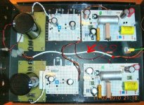
As promised a photo with one Salas Super-Shunt regulator feeding two Salas Phono RIAA.
An externally hosted image should be here but it was not working when we last tested it.
Which Xfrm did you order from Mouser? 229D40?
Yes like tese two:
An externally hosted image should be here but it was not working when we last tested it.
Workable for now, nice clean build with very good components in general. Of course shorter cables later when with two shunts operating will be better, and then remote sensing of course. How did you kill one tx by the way? If you experience any hum from GND loops, or from the AC cabling running across meanwhile don't pay much attention before you would have the final arrangemend to debug anyway. Have a happy initial listening. Good job.
Yes like tese two:
I'd like to buy them...... can you tell me Vin and Vout?
(I mean 230 and 40 V AC) Thanks.

Can arrange the rectification/cap filter boards in the external box with the transformers latter on I guess.
Hello Salas,
I've selected the 2sk170 for the circuit of the post 2795 and they are from 8,1 to 8,3 mA selected in pairs plus one quad for the first stage Q1 Q7.
My input is 0,4mV and i don't use C10.
How I must modificate the resistors of the schematic for the correct gain?
Thanks a lot
Guglielmo
I've selected the 2sk170 for the circuit of the post 2795 and they are from 8,1 to 8,3 mA selected in pairs plus one quad for the first stage Q1 Q7.
My input is 0,4mV and i don't use C10.
How I must modificate the resistors of the schematic for the correct gain?
Thanks a lot
Guglielmo
Thanks, I have no room in Tx boox to mount the PS, the idea is in one box the regs. & phono & in other box the Tx & PS. I kill the Tx due to a wrong connection (are dual: primary 115-230 & secondary 20V/2.4A-40V/1.2A so I wired wrong) & when connected the Tx do a lot of noise. Tomorrow I will hear.
An externally hosted image should be here but it was not working when we last tested it.
I'd like to buy them...... can you tell me Vin and Vout?
(I mean 230 and 40 V AC) Thanks.
Primary 115 or 230V
Secondary 20V/2.4A or 40V/1.2A so 48VA
Mouser ref. 546-229-D40, price 14€44 each
Last edited:
Good gob
but as you use two box ,why put the AC on signal box ?
Edit
ops Salas just note this...
Thks, it's provisional, I don't have room in the Tx boox, mine idea is 2 boxes, one for regs. & phono & the other for PS & Tx as usually do.
can arrange the rectification/cap filter boards in the external box with the transformers latter on i guess.
yes.
Primary 115 or 230V
Secondary 20V/2.4A or 40V/1.2A so 48VA
Mouser ref. 546-229-D40, price 14€44 each
Yes, thank you. I knew those info. I was asking you the real value measured when loaded at 250 mA (or so) by the CCS 🙄
Hello Salas,
I've selected the 2sk170 for the circuit of the post 2795 and they are from 8,1 to 8,3 mA selected in pairs plus one quad for the first stage Q1 Q7.
My input is 0,4mV and i don't use C10.
How I must modificate the resistors of the schematic for the correct gain?
Thanks a lot
Guglielmo
Here you are, for your special situation.
Attachments
Yes, thank you. I knew those info. I was asking you the real value measured when loaded at 250 mA (or so) by the CCS 🙄
Sorry how can do to tell you the information requested?
- Home
- Source & Line
- Analogue Source
- Simplistic NJFET RIAA