Thank you Salas
You made it perfectly clear to me now.
Maybe I will use a 220uF BG on the output.... I really like BG sound.
Regards
Ricardo
You made it perfectly clear to me now.
Maybe I will use a 220uF BG on the output.... I really like BG sound.
Regards
Ricardo
Kalimera, Kirie Salas!
Just one question about your shuntreg: why did you use such a beefy TO247 mosfet for the CCS and the parallel device? It's only 120 mA for the first one and much less for the second. Wasn't a TO220 mosfet (such as IRF9610) enough for this purpose?
(OK, OK, I know one possible answer: I picked up what was available in my drawer.....)
P.S. I like the idea of a P device for the shunt, while many others use N devices that amplify the noise.
Beefy usually sounds...errr...beefy.🙂 Plus it will not create instability so easily as a very fast one, plus low Rds On (9610=3 Ohm, 9240=0.5 Ohm). In my initial concept explanation I talked about faster TO220 Mosfets too and that many devices will do. Open to experiments. Also we may run Amperes even if we feel like spending money and space on transformer and heatsinks. It will sound different maybe. Also 9240 has good availability.
As it is now, the sound opens very noticeably in dimensional scale, cleans up a lot, the focus of each instrument becomes very certain, and the overall musical detail gain is breathtaking.
The concept is easy, please experiment with Mosfet types and capacitor values and qualities as much as you can.
One last thing. For those who are going to use RIAA versions requiring under 30V B+ better use 4.7k resistors for the current source BC560 instead of the 6.8k ones in the 37V B+ example. That way its current stays about the same level as in the example. Taken that the Vin is +6 to 8V up Vreg.
And a hint. Auricaps sound nicely warm and beefy at the final output coupling capacitor position in my RIAA. But that is a system match and preference area. You know all that.
And a hint. Auricaps sound nicely warm and beefy at the final output coupling capacitor position in my RIAA. But that is a system match and preference area. You know all that.
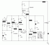
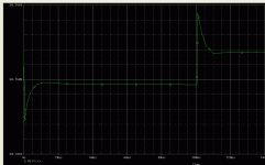
Here are the simulation results. The regultor is fast, low impedance, and should be pretty low noise. Whys and wherefores will follow when I feel like writing them. In the meantime, dissect it into component functional blocks and think about it for a bit.
Attachments
wrenchone said:Here are the simulation results. The regultor is fast, low impedance, and should be pretty low noise. Whys and wherefores will follow when I feel like writing them. In the meantime, dissect it into component functional blocks and think about it for a bit.
Some friends are substituting adjustable shunt regulators for zeners in their microphones. Any thoughts? It's nice having one part for all voltages, no TC, much less noise, very low min current.
Today I finally found time to build this circuit. Unfortunately, I am not getting any sound output.
Being pretty noobish, I have a noobish question if you don't mind. I'd just like to check that I have the FET's and transistor the correct way round. Which pins on Q6 are tied together please? And is it pin 1 of Q3 (bc550) that connects to Q1?
Cheers, Lee.
(Confused as to why it won't work)
Being pretty noobish, I have a noobish question if you don't mind. I'd just like to check that I have the FET's and transistor the correct way round. Which pins on Q6 are tied together please? And is it pin 1 of Q3 (bc550) that connects to Q1?
Cheers, Lee.
(Confused as to why it won't work)
mikvous said:Lee,
Which version are you trying.Don't worry we'll find it
Hi there. It is this one
Regards, Lee.
Hi, it is possible that your last Q (buffer NJFET) has higher than calculated Idss and drops its Vd too much, Vg under its Vs, so it won't work. Given that all your parts are correctly oriented (most possibly) I would use a smaller resistor on its RC filter (R20) maybe 470R, same for R19, and see if I get sound. Measure the DC on its gate and source please. See that the gate sits slightly higher than the source.
Thomo said:Today I finally found time to build this circuit. Unfortunately, I am not getting any sound output.
Being pretty noobish, I have a noobish question if you don't mind. I'd just like to check that I have the FET's and transistor the correct way round. Which pins on Q6 are tied together please? And is it pin 1 of Q3 (bc550) that connects to Q1?
Cheers, Lee.
(Confused as to why it won't work)
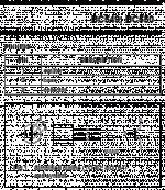
As you watch the 2SK170 upright looking at its flat face, the 2 right legs tie together for Q6. From left to right, D G S. As for the BC550 see the attachment.
Attachments
Hi Salas, thanks for your help. The voltage on Gate of Q5 is oscillating wildly from ~4v - ~12v. Source is ~9v.
I matched these fets using the method shown in an earlier post, and this is making me question the accuracy of my meter.
I will try as you suggested and reduce the value of those two resistors.
Regards, Lee.
I matched these fets using the method shown in an earlier post, and this is making me question the accuracy of my meter.
I will try as you suggested and reduce the value of those two resistors.
Regards, Lee.
I re-checked all joints and now get a loud hum and very quiet music. Which is better than before, lol.
All connections are good, so it must still be something else.
Regards, Lee.
edit: Vd is ~14v so yep, higher than source.
All connections are good, so it must still be something else.
Regards, Lee.
edit: Vd is ~14v so yep, higher than source.
- Home
- Source & Line
- Analogue Source
- Simplistic NJFET RIAA


