

Any changes to the circuit posted in #2061? Any part changes?
47uF before the regulator
20VDC headroom
minimum 20mA extra current
20mA (assuming minimum is used) * final B+ dissipated by Q3
Q1 dissipates (20mA + load current) * 20VDC headroom
47uF before the regulator
20VDC headroom
minimum 20mA extra current
20mA (assuming minimum is used) * final B+ dissipated by Q3
Q1 dissipates (20mA + load current) * 20VDC headroom
That's quite the testament to your design! Congrats! Given a 20mA load could I get away with 15 mA - 18mA shunt current instead of the recommended 20mA?
You could, it will only be bit worse in spec, but no tragedy. Run it at even 30mA spare when you will have the sinking, the change is audible enough form 15mA.
You gotta scale down the two same value I/V resistors R9,R10.
Will give it a try, thanks! 😉
I see this confusing...minimum 20mA extra current
20mA (assuming minimum is used) * final B+ dissipated by Q3
20mA extra current is above MAX (amplitude) current, not quiescent current, so the dissipation for Q3 should be (20mA -5mA +(Imax - Io))*Vb+,
where
Imax - amplitude current
Io - quiescent current
Vb+ - final B+
5mA - this current is reserved by BJT cascode and sensing circuit.
Last edited:
I see this confusing...
20mA extra current is above MAX (amplitude) current, not quiescent current, so the dissipation for Q3 should be (20mA -5mA +(Imax - Io))*Vb+,
where
Imax - amplitude current
Io - quiescent current
Vb+ - final B+
5mA - this current is reserved by BJT cascode and sensing circuit.
thank you for the correction. Assume the circuit below the regulator can be modeled as a constant current source. Then, is Imax-Io zero? Then the power dissipated is (20mA-5mA) * Vb+?
If the circuit can be seen as CCS - then - yes.thank you for the correction. Assume the circuit below the regulator can be modeled as a constant current source. Then, is Imax-Io zero? Then the power dissipated is (20mA-5mA) * Vb+?
Several pages ago there was a discussion about "class A" and its "constant current" capabilities. But as you can see the constant current model for the circuit is not constant at all. "Constant" here is the quiescent current.
Now?
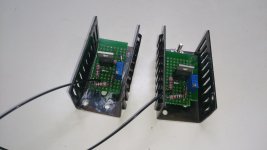
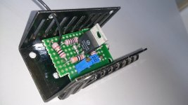
I have finally made a pair of this CCS.......and tested them at 12V DC...to be working fine...
I have changed R3 to be 500R....so I could have a bit lower current....even with 500R as R3, only one CCS goes as low as 9mA, while the other one only goes to 14mA.....so I think I will use 600R for R3 to get low as around 10mA for both....
Next is to test them in my line amp which my friend still has....
Cheers....
****
Attachments
I have finally made a pair of this CCS.......and tested them at 12V DC...to be working fine...
I have changed R3 to be 500R....so I could have a bit lower current....even with 500R as R3, only one CCS goes as low as 9mA, while the other one only goes to 14mA.....so I think I will use 600R for R3 to get low as around 10mA for both....
Next is to test them in my line amp which my friend still has....
Cheers....
****
Congrats😉
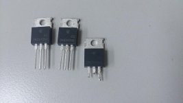
I have bought a pair of fake DN2540 (please see photo) from a supplier in Hong Kong....
But he sent replacement.
I only bought in USA: Mouser DN2540N5-G Supertex | Mouseror Ebay Uk dealer 2 x Supertex DN2540N5 DN2540 Depletion Mosfet DIY CCS | eBay
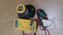
The above 12V DC test was done with no load....just measuring voltage across the 10R resistor as in your diagram....do you think the current will drop with a load (a VT-25A tube)??
***
If I buy from outside HK, the freight is more than the item most of the time, as I only buy small quantity at a tiem....
But that supplier made good by sending good replacement.....that is not bad either...
Cheers....
***
If I buy from outside HK, the freight is more than the item most of the time, as I only buy small quantity at a tiem....
But that supplier made good by sending good replacement.....that is not bad either...
Cheers....
Better connect a dummy load and before the CCS connect in series 100 ohms resitors measure the current accross the 100 ohms resistor and you will adjust the CCS current, once adjusted you can disconnect the 100 ohms resistor. Enjoy🙂
Shall do....thankyou....
May be able to take the pair to my friend's house this afternoon, to have the real test as well...
Will report back if that happens...
😛
May be able to take the pair to my friend's house this afternoon, to have the real test as well...
Will report back if that happens...
😛
This evening I connect the CCS direct to tube as load....I can only get 9mA for each CCS....and no sound from the line amp (only distorted music at very high volume)....😱😱
I can only put it to not enough mA to the tube......
Could that have been of other mistake I made??😕😕
***
Next week, I will work with the 100R dummy load to get 10-25mA range for the CCS when loaded...and try again with the tube again later...
***
Any thoughts and suggestions welcome.
Cheers...
King
- Home
- Amplifiers
- Power Supplies
- Simplistic mosFET HV Shunt Regs