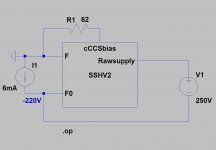
Will the SSHSV2 design in the latest group buy be able to produce a negative supply voltage as above with some parts changes?
Thanks
Possibly in p2p for one, not on the positive board, but I haven't looked into it because I prefer this scheme, which is anti ground loop also:
Attachments
Having trouble finding LEDS 2Vf @ 5mA.
Any types recommended?
Thanks
Any generic green 3mm will serve you well. That question was for SSHV1 I assume.
Possibly in p2p for one, not on the positive board, but I haven't looked into it because I prefer this scheme, which is anti ground loop also:
This is different rectifiction layout that allows use of dual standard SSHV2?
With that one you can arrange into +/-V any positive only raw PSUs or regulators be it chip, discrete, low voltage, high voltage, whatever. NAIM NAP 250 bolt on original was like that when I serviced one.
Can't be done with two independent transformers. Common primary, two secondaries, single transformer, two bridges.
Any generic green 3mm will serve you well. That question was for SSHV1 I assume.
Yes the SSHV1
Why? 😕Can't be done with two independent transformers. Common primary, two secondaries, single transformer, two bridges.
No.The scondaries should be correlated.
the dual secondaries of a transformer are isolated. They are not "correlated". The dual secondary transformer creates two independent supplies.
These two supplies are then connected at some common point.
Using two transformers, each with an isolated secondary, achieves the same dual supplies that can be connected at some point.
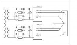
post2722Possibly in p2p for one, not on the positive board, but I haven't looked into it because I prefer this scheme, which is anti ground loop also:
It would be better to continue the sense lines separately all the way to the load. The +ve Hot and -ve Hot are both shown separate. The +ve Cold and -ve Cold should be shown the same.
No.
the dual secondaries of a transformer are isolated. They are not "correlated". The dual secondary transformer creates two independent supplies.
These two supplies are then connected at some common point.
Using two transformers, each with an isolated secondary, achieves the same dual supplies that can be connected at some point.
All to the better then because even single secondary spare transformers can be used. Although somehow I had this differently registered in mind, I hope its exactly the same as with a common primary as I have only seen it in builds. This uses more components, and losses are higher because of the extra diodes, but this scheme offers easier ground management. It's easier to keep the large charging current pulses away from the system ground.
I have tried, using my limited resources, to measure the difference between dual bridge PSU and centre tapped+single bridge PSU for an effect on hum and noise and rail ripple.It's easier to keep the large charging current pulses away from the system ground.
I cannot measure a difference.
I have tried, using my limited resources, to measure the difference between dual bridge PSU and centre tapped+single bridge PSU for an effect on hum and noise and rail ripple.
I cannot measure a difference.
The key word is ''easier'', if the system ground is managed already very well there will not be much to improve on.
Can you use a dual polarity supply with single bridge to power dual SSHV2'.
For symmetric +/- with positives no. For more than one positives as positives yes.
- Home
- Amplifiers
- Power Supplies
- Simplistic mosFET HV Shunt Regs