Merlin see what's wrong feeding, grounding, or loading the regs. Something's fishy when two different ones give smoke.
I tested again the separate PSU and seems all OK
CLC, the last C is in the same quanghao reg 300uF
Attachments

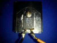
Using so heavy last capacitor, why? Are your fins insulated between them? Maybe they touch?
quanghao pcb caps are in parallel.
dvb-projekt connected without cap at the input reg.
Ask again, did test with dummy first?
No I did test with dummy load because burned, wich value in ohms & watts?
You burned the dummy load? 15k 10W is a good allrounder.
Also I think you know you shouldn' t test the regs without a load.
Also I think you know you shouldn' t test the regs without a load.
NO I didn't burned the dummy load. Yes I know it's necessary to use a dummy load or the circuit, but the Puresound phono MM was going on perfectly well with other 240VAC tx, I only changed the tx so I supposed that all will go OK that's the reason I didn't used a dummy load but the reg was connected to the MM.
Last edited:
Merlin see what's wrong feeding, grounding, or loading the regs. Something's fishy when two different ones give smoke.
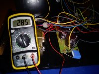
There is other way to test the Vin 284VDC than a DVM?, because with multimeter seems voltage OK.
1% resistor is not necessary for dummy.
Better transformers, sometimes have better regulation, so more Vin under load. I would put a resistor in front, say 500R on next try, just to be safe and check Vin and not to have too much drop on the shunt, and not to burn anything.
Better transformers, sometimes have better regulation, so more Vin under load. I would put a resistor in front, say 500R on next try, just to be safe and check Vin and not to have too much drop on the shunt, and not to burn anything.
A shunt regulator is safe without a dummy load.
The CCS half supplies constant current. Other than slight variations with temperature changes, you can never get more current through the CCS.
The Shunt then draws current. If the current from the CCS exceeds the load current and the shunt current then the output rises. The shunt adjusts and when the shunt current + the load current = CCS current the shunt is regulating the output voltage.
If the load current drops to zero the output voltage rises and the Shunt adjusts to draw more current and the voltage drops back to the regulated voltage.
If the CCS + Shunt cannot survive an open circuit output then the components have been chosen badly.
A CCS + Shunt regulator is virtually bombproof. Nothing outside the regulator can ever damage a properly built shunt regulator.
Yes I know is'nt necessary 1% resistor as dummy load but I have on my stash so I will use instead to buy a new one. 500R instead 47R or in series with B+?
Tx
rendering 90%
regulation 0.5%
Ampere 0.505 for 220 - RDC Ohms 11
primary RDC ohms 11
relation primary 230 / secondary 220 = n. 1,0455
relation n 1,0455 to the square 1,093
primary RDC ohms 11
relation n. to the square 1,093
source resistance 20 ohms
Tx
rendering 90%
regulation 0.5%
Ampere 0.505 for 220 - RDC Ohms 11
primary RDC ohms 11
relation primary 230 / secondary 220 = n. 1,0455
relation n 1,0455 to the square 1,093
primary RDC ohms 11
relation n. to the square 1,093
source resistance 20 ohms
500R in series with B+. If Vin is too low, nothing gets burned, just can' t regulate. Then you can lower this resistor to reach desired Vin.
Of course, you can simulate all this with PSUD2. Then you will now before you try!
Of course, you can simulate all this with PSUD2. Then you will now before you try!
The other tx used before was 240VAC, now the new Bartolucci only have 200VAC, really I don't understand nothing & I don't know the reason of issue, there is other way to test Vin 284V coming from the PSU that isn't a DVM?
Sorry my ignorance wich value to simulate "for value in ms" and for "after a reporting delay of value in S"?
Using 1000 for value in ms and 1 for value in S the voltage after the reg is 285V I do something wrong?
Using 1000 for value in ms and 1 for value in S the voltage after the reg is 285V I do something wrong?
Last edited:
Watch it with high voltage when debugging, keep one hand in your back pocket. Certainly watch out for gross stuff like accidentally shorting an HV line and the like. Better wear eye protection.
I have CLC, tx is Bartolucci 200VDC choke is Bartolucci 10H 100mA, all caps are lytics C1 660uF 450V & C2 300uF 350V
Can the capacitors be too heavy kicking high spikes?
- Home
- Amplifiers
- Power Supplies
- Simplistic mosFET HV Shunt Regs