Increase in HV
I use the Salas reg as in this schematic. Is it ok if I increase the Vin from 215V to 240V without doing anything to the regulator. As I see it the current draw will still be about 36mA. I have a big heatsink and the temperature is very nice today, about 40C I think.
I use the Salas reg as in this schematic. Is it ok if I increase the Vin from 215V to 240V without doing anything to the regulator. As I see it the current draw will still be about 36mA. I have a big heatsink and the temperature is very nice today, about 40C I think.
Attachments
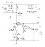
Increasing the current to 50mA will bring you more benefit for lowering the Zo than just heating up the CCS Mosfet with more Vin-Vo since you got the sink.
bipolar 300v reg news
i ve been giving juice to my exstata (The eXStatA Electrostatic Amplifier) with my prototype bipolar salas reg for a handful of hours now and so far i have not noticed any sign of oscillation or malfunction and it sounds great (how surprising? 😉). in the meantime i ve been working on a final compact version but i cant make it work. but i highly suspect the problem comes from some kind of mishandling from me 🙂. i ll give updates when i try to debug it. as usual, pictures not available🙁 ...for now
i ve been giving juice to my exstata (The eXStatA Electrostatic Amplifier) with my prototype bipolar salas reg for a handful of hours now and so far i have not noticed any sign of oscillation or malfunction and it sounds great (how surprising? 😉). in the meantime i ve been working on a final compact version but i cant make it work. but i highly suspect the problem comes from some kind of mishandling from me 🙂. i ll give updates when i try to debug it. as usual, pictures not available🙁 ...for now

So I must change that CCT's title from SSHV negative theoretical, to SSHV negative practical.😀
Hi Salas,
is there any issue wiring this P2P?
It's difficult to get a hold of QH for pcb.
for 40mA current, is 57.5ohms (1W) correct for R1?
5.4V(LED voltage) - 3.1(IRF9240) / 40mA?
the 1K trimmer is to adjust voltage? if my trafo is 230V into FWB, my
target voltage is 200-210V.
Is this HV shunt overkill for Aikido Cathode Follower? I'm using ACF w/6DJ8's.
which schematic should I be using? QH's schematic calls for IRF9610.
thanks!
No issue, I make it p2p only.
Current target is always ballpark for R1 given the Vgs of each Mosfet sample in circuit's actual voltage, and Leds total Vf. A check of R1's voltage drop across it divided by its value will give the real life current and will let you trim its exact needed value.
Looks like you will be dropping much voltage across the CCS Mosfet with a 230VAC Tx and 200V Vo. Use CRC and leave only 20V to drop. Saves on silicon's dissipation, increases long term reliability, pre filters.
In my experience its not overkill even if a good reg is there already (bypass it) or there is a good PSRR inherent scheme in the audio client CCT.
9610 proved reliable too and its the ''faster'' CCS choice. Don't forget to target about 25mA above your top load demand for setting CCS mA.
Regards.
No issue, I make it p2p only.
Current target is always ballpark for R1 given the Vgs of each Mosfet sample in circuit's actual voltage, and Leds total Vf. A check of R1's voltage drop across it divided by its value will give the real life current and will let you trim its exact needed value.
Looks like you will be dropping much voltage across the CCS Mosfet with a 230VAC Tx and 200V Vo. Use CRC and leave only 20V to drop. Saves on silicon's dissipation, increases long term reliability, pre filters.
In my experience its not overkill even if a good reg is there already (bypass it) or there is a good PSRR inherent scheme in the audio client CCT.
9610 proved reliable too and its the ''faster'' CCS choice. Don't forget to target about 25mA above your top load demand for setting CCS mA.
Regards.
Thanks Salas.
actually I'm using the BAS PSU with 6xGT and CRC. So getting it to 220V
before the shunt is no problem.
the 6DJ8 pair is 20mA so I factor in the 20mA as you mentioned to double up or higher. I'm using a hammond 229 trafo, max rating is 230V @ 50mA.
is there a way to check for correct voltage/current without a load on the shunt?
Thx
Dummy load. 10K Ohm 10W. 20mA draw & 4W self dissipation if across 200V. It will be setting correctly for CCS mA and Vo without, but the dissipation for the load is going to add on the IRF840's sink.
should R1 and other resistors be 1% MF? or use 5% metal oxides for higher wattage?
I have a 10K 8W, should do the job for the dummy load.
thanks
I have a 10K 8W, should do the job for the dummy load.
thanks
should R1 and other resistors be 1% MF? or use 5% metal oxides for higher wattage?
I have a 10K 8W, should do the job for the dummy load.
thanks
R1 need be no super quality or tolerance spec. R4 is the ref and only that one better be best ppm and quality.
Hi Salas,
the bas psu right now I have set at +209V using 1K + 1K for 20mA(two 6DJ8).
So I need to put a dummy load (5K) for 40mA and adjust the resistors for 220V before I even connect to the shunt circuit?
I will stick with the IRF9610. Do you know what the gate voltage would be?
for 40mA load, R1 is 57.5ohms with 3.1V gate voltage, that was based on your orignal post with irf9240, I think.
I want to get a few resistos for R1 and at least be in the ball park 🙂
Thanks.
Know your load and have it set at the bias point you aspire to.
If your load will be 20mA then you need to use a setting dummy for 20mA. The rest runs the shunt, stays in.
3.4-4V usually.
That Vgs was for a certain other type, sample, and working conditions. You can't predict exactly else you measure a batch in analogous voltages tests. Plus the Leds will vary from spec. Use a rule of thumb. Say 2V/R1. Try a 47R. It will be safe.
I'm probably not asking correctly. To properly adjust the Bas PSU CRCR for 220V, does the BAS PSU see 40MA or 20MA with the Shunt Circuit connected?
Thanks.
Thanks.
40mA test to know your final drop over CRCR with 40mA CCS shunt reg. Then again its just Ohm's law, you could calculate.
If I use a linear Volt. Reg. (eg. LM1084) in front of the shunt circuit, does that defeat the shunt's value of low noise,etc...?
Thanks.
Thanks.
Its pre regulation. Its OK for even improving spec. Must float, and I would not subjectively prefer more and internally complex circuitry over a passive pre filter.
Hello Salas, after reading 120 pages of thread (whew!😀) few question just to clear my mind..
i'll be using the sshv for the aikido pre i'm building, load will be 40mA, ps filter will be CRCLC.. i was going to use just crc as suggested but i decided to add an rc cell to drop voltage to 300v, please correct me if i'm wrong:
R1=22r for 80mA load, that's pre current needs x 2
R3=68k for 300v Vin or 56K?
led trio drop from 5.4 to 5.7
shorter connection possible from regulator to load
after populating the pcb and triple check for everything, start with trimmer halfway, 500r or 1K? or like piero7 even a 100r one?
thanks for your time and work!
i'll using this scheme:
Attachments
- Home
- Amplifiers
- Power Supplies
- Simplistic mosFET HV Shunt Regs