Salas,
Could it be possible to make a reg. with 285v @ 150mA ??
Albert
Possibly, the setting range is there, but the radiated heat to the smaller semis can turn it unstable. If much of that 0.15A goes to the load constantly, rather passable. I would do it point to point on air, so the elements can have max air circulation around them. Adequate sinking provisions, it goes without saying. If it is to see an inductive load, then again another difficulty, usually a dead end. Another thing, if there are B+ local decoupling capacitors of any value on the rails at the load side, use 100R in series before them to form a basic RC. That buffers them and keeps the regulator's bandwidth & phase margin safe. Or take them out all together. This is a general hint to all users.
Having an issue with high ripple on the output of the SSHV.
Each channel has a dedicated 50VA transformer and prefilter = 330V-50uf-5H-50uf-1.47k-5uF.
Separate SSHV per channel (both behaving the same.)
SSHV:
R1=46 ohm =2V drop = 40 mA
Output = 170V 16mA.
Test with a 10K in series with a 1 ohm resistors across the output.
Measuring AC across the 1ohm resistor gives 16mV of AC.
I believe it to be 60hz as I have a nice spike at 60hz when measuring the amp with RIAA/soundcard (no scope).
All LED's light up. Q1 gets warm, Q2 runs about 180F. Voltage adjusts up and down fine. Verified the zobel cap had good connections.
Any ideas?
Try with 1Meg and 100R or with just a scope or FFT AC coupled and no divider (danger to kill a card on a wrong move). 10K and 1R probably upsets the termination. What you see on FFT could be partly a ground loop also. The regs can be healthy.
Try with 1Meg and 100R or with just a scope or FFT AC coupled and no divider (danger to kill a card on a wrong move). 10K and 1R probably upsets the termination. What you see on FFT could be partly a ground loop also. The regs can be healthy.
Salas my circuit has a 1 ohm resistor before the plate stopper for easy tube biasing.
I measure 16 mV across this when the circuit is powered up. Are you saying this measurement error with the fluke, or should I remove ththese 1 ohm resistors at the plates because they are a problem for the SSHV?
I do think a ground loop is more probable, I mean if I really had 16mV of ripple on the plate it would likely be lot wrose than a -80dB peak at 60hz.
Time to buy a new scope anyhow.
Thanks
Possibly, the setting range is there, but the radiated heat to the smaller semis can turn it unstable. If much of that 0.15A goes to the load constantly, rather passable. I would do it point to point on air, so the elements can have max air circulation around them. Adequate sinking provisions, it goes without saying. If it is to see an inductive load, then again another difficulty, usually a dead end. Another thing, if there are B+ local decoupling capacitors of any value on the rails at the load side, use 100R in series before them to form a basic RC. That buffers them and keeps the regulator's bandwidth & phase margin safe. Or take them out all together. This is a general hint to all users.
Salas,
Will it work if I go R1 12R 2w, R3 56k 2w and R4 120k 2w
Albert
Salas my circuit has a 1 ohm resistor before the plate stopper for easy tube biasing.
I measure 16 mV across this when the circuit is powered up. Are you saying this measurement error with the fluke, or should I remove ththese 1 ohm resistors at the plates because they are a problem for the SSHV?
I do think a ground loop is more probable, I mean if I really had 16mV of ripple on the plate it would likely be lot wrose than a -80dB peak at 60hz.
Time to buy a new scope anyhow.
Thanks
I thought you just used a 10k & 1R divider across the output. Now you say an audio circuit is involved. If 60Hz is on the grid, it will modulate the current drawn across the 1 Ohm. So the 10K is not an original part, but now it drops the plate voltage? Too many factors. What to do is to apply a scope across the DC rail when feeding the original audio circuit load and just see a thin DC line and no appreciable AC component. 16mV ACRMS @ 60Hz is 45mV PP. But 45mV peak to peak 60Hz would be humming audibly I guess first of all. Is there any hum?
Salas,
Will it work if I go R1 12R 2w, R3 56k 2w and R4 120k 2w
Albert
12R could shoot lower or higher than 150mA, depends on your LEDS and Mosfet VGS, but its good ballpark to start. Make R3 68K 5W and R4 3W.
12R could shoot lower or higher than 150mA, depends on your LEDS and Mosfet VGS, but its good ballpark to start. Make R3 68K 5W and R4 3W.
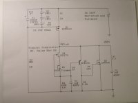
Thanks and please take a look at the pictures and advice would be appreciated.
Albert
Attachments
Last edited:
Looks OK. An idea is you may add a red LED between the 500R trimmer/gate node and R4, orientation as the other ones, it maybe can help a bit the Vbe drift by lending some negative coefficient since your temp is gonna be high around the components at 150mA. It will be signaling there is output voltage as a ''bonus''. I don't remember anyone attempting it so high mA at so high voltage so I hope it will not be kicking at turn on or something and it will work for you. What is it for, and how high will the constant load be in mA?
Attachments
Looks OK. An idea is you may add a red LED between the 500R trimmer/gate node and R4, orientation as the other ones, it maybe can help a bit the Vbe drift by lending some negative coefficient since your temp is gonna be high around the components at 150mA. It will be signaling there is output voltage as a ''bonus''. I don't remember anyone attempting it so high mA at so high voltage so I hope it will not be kicking at turn on or something and it will work for you. What is it for, and how high will the constant load be in mA?
Firstly thanks for the detail reply.
I'm planing to make a new pair of 300bxls with 14w output. I did build one at about 4 years ago with big success. I really would like to try regulated supply for the 300bxls power tube. It drains about 120mA and the CCS 6H30 with will again take about 25-30mA, depends how hot I'm going to run it.
That means you really need 175mA so to leave the +25mA for the reg proper operation which are essential to it. The 9610 will exibit more Vgs than the usual 4V we see at 50mA settings. It will take low enough R1. Around 8R2 with 6V LEDS total drop. If the LEDS will not achieve 6V total @ 5mA they get in circuit, then R1 can be even lower for 175mA. You should check the actual running current by VR1/R1=Iccs. That will create about 7W dissipation on the output Mosfet sink plus 6W on the input Mosfet sink. Not bad. But driving a transformer at such current its not what it is designed for. So it may fail due to dynamic inductive loading. But its not an expensive circuit to experiment with. If it will succeed it will make it a special amp. At least you may relegate it to the 6H30 input stage with ~50mA CCS in case it won't marry to the OPT. It will still make a good difference for overall quality.
P.S. Don't try it unloaded, then the whole 0.175A times 285V will try to dissipate on the output sink. 50W.
P.S. Don't try it unloaded, then the whole 0.175A times 285V will try to dissipate on the output sink. 50W.
I thought you just used a 10k & 1R divider across the output. Now you say an audio circuit is involved. If 60Hz is on the grid, it will modulate the current drawn across the 1 Ohm. So the 10K is not an original part, but now it drops the plate voltage? Too many factors. What to do is to apply a scope across the DC rail when feeding the original audio circuit load and just see a thin DC line and no appreciable AC component. 16mV ACRMS @ 60Hz is 45mV PP. But 45mV peak to peak 60Hz would be humming audibly I guess first of all. Is there any hum?
First I found the 16 mV AC across the 1 ohm resistor in the audio circuit which is simply at the plate of the tube which is drawing 16mA @170V. It is there only to bias the tube easily.
So I removed the regulator from the ciruit and hooked up a 1R+10k resistor to test the SSHV, that is when I found the same 16mV AC across the 1 ohm test resistor.
What I think you are saying is my archaic test procedure is flawed due to termination issue with the fluke DMM 😱
No, the hum is not audible but measureable at -80dB with a soundcard. I think if there really were 16mV AC ripple on the SSHV output it would be very audible I calculate at least -40dB if it were truly there.
So I think I can say definate ground-loop issue. I was just surprised to find AC on the SSHV output with just a 10k in series with 1R - setup for testing.
thanks again
There shouldn't be any. I am trying to get the whole picture. Do you have 1M+100R to do the same test? That would be a double check.
That means you really need 175mA so to leave the +25mA for the reg proper operation which are essential to it. The 9610 will exibit more Vgs than the usual 4V we see at 50mA settings. It will take low enough R1. Around 8R2 with 6V LEDS total drop. If the LEDS will not achieve 6V total @ 5mA they get in circuit, then R1 can be even lower for 175mA. You should check the actual running current by VR1/R1=Iccs. That will create about 7W dissipation on the output Mosfet sink plus 6W on the input Mosfet sink. Not bad. But driving a transformer at such current its not what it is designed for. So it may fail due to dynamic inductive loading. But its not an expensive circuit to experiment with. If it will succeed it will make it a special amp. At least you may relegate it to the 6H30 input stage with ~50mA CCS in case it won't marry to the OPT. It will still make a good difference for overall quality.
P.S. Don't try it unloaded, then the whole 0.175A times 285V will try to dissipate on the output sink. 50W.
Very good hint. I have the same worry have it to drive the transformer too. Will certainly let you know if I decide to go ahead. You really have a good point on doing this for 6H30. I had the 10M45s on now, good to try and see.
Thanks
Probably it has been asked several times already, but this thread is too long....
Is there any chance to get 425V out of this reg? It is for a C3m driving a 300B, current is around 15mA. I've read that 400V are possible, but...unfortunately more is needed to have the full swing to really kick the fat ladys bottom.
Any suggestions?
Is there any chance to get 425V out of this reg? It is for a C3m driving a 300B, current is around 15mA. I've read that 400V are possible, but...unfortunately more is needed to have the full swing to really kick the fat ladys bottom.
Any suggestions?
Does your project deserve careful thought? Research your project and your proposals and give the project a chance of succeeding.
MJE350s are rated 300V @ 1mA and they had been used in cascode in this reg, has been done before in the thread. So theoretically the output max can be boosted. If it will take the input on transient CCS wise for circa 450V DCin, how the MJEs or the FET will hold on C2 charge up etc. No body knows until an experiment. If you wanna check it out, its not an expensive BOM project.
If you wanna check it out, its not an expensive BOM project.
O.K., hopefully its no BOOOM project either....so no experiences so far it seems. As far as I can see fo such high voltage MJE5731A or MPSA94 is preferred by some people. Have to search for these, but have enough IRF and sk170 already.
Other safer thing would be to feed the screen of the pentode, needs around 150V/3mA, which also means less heat in the enclosures.
The amps are already running btw and sound very good, with amorphous OPT and AVVT 300B. But the shunt should just give it more of everything.
If it works, I will report of course, but will take some time...
Cheers,
Juergen
- Home
- Amplifiers
- Power Supplies
- Simplistic mosFET HV Shunt Regs