Thanks, Salas.
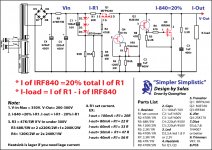
Concerning the circuit on post #907, 8mA (Q4) on 200kohm (R4, R10) will drop 1,600V, so one of the two values is wrong.
No, 8ma its the free IDSS rating with a 9V battery test. The trimmer between g,s takes it down and gives us the Vout setting choice. It can even be a higher value trimmer. An 8mA IDSS 2SK170BL gives about 2mA with around 100R between g,s for instance at this circuit's VDS, under the BJT margin that is snugged in, and protected.
Here are all my practice “Simpler Simplistic'', please see,
Thanks a lot Salas!!!
Quanghao
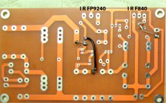
And the Board finis !,But it is wrong! you can see please!
Attachments
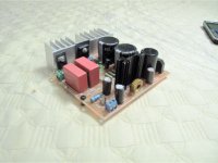
Hi, Quanghao, forgive my ignorance, but what is this donut shaped thing on the board, at the heatsink opposite side?
Hi, Quanghao, forgive my ignorance, but what is this donut shaped thing on the board, at the heatsink opposite side?
That small choke should be in the Heater PS section of the pcb, not in the Salas' shunt.
Hi, Quanghao, forgive my ignorance, but what is this donut shaped thing on the board, at the heatsink opposite side?
Coil.
It isn't in the parts list, nor in the schematic..
Read what I wrote: not in the Salas's shunt circuit
😉
Read what I wrote: not in the Salas's shunt circuit
😉
This means that the real Simpler Simplistic starts at the positive leg of C1?
He just combines an independent low voltage heater supply on the same board of his. Using it for whatever.
I see a lot of potential for confusion and sparks; the circuit lends itself very well to point-to-point wiring. This will also force you to read the schematic carefully and check your work well. Using someone's less the thorough tested pcb is quite risky.
That small choke should be in the Heater PS section of the pcb, not in the Salas' shunt.
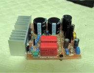
Hi! that is my filament
You can see in the image!
Attachments
Sorry, I still can not see a clear answer on this. Let me expose it in another way.
Suppose that one just want to use the regulator stuff, and want to have the raw DC supply completely off board, in case of using your board, is it to be filled starting at C1, while ignoring everything that comes first on the schematic of post 943...?
Suppose that one just want to use the regulator stuff, and want to have the raw DC supply completely off board, in case of using your board, is it to be filled starting at C1, while ignoring everything that comes first on the schematic of post 943...?

Sorry but yesterday when you asked first I couldn't open schem of post #943 (don't ask me why) and thus identify C1.
Anyway pics and schematics on page 1 tell you all.
Drink a mate for me! 😉
Anyway pics and schematics on page 1 tell you all.
Drink a mate for me! 😉
It has been sometime since the low voltage (+18.6V & -18.6V) regulators were posted.
Are there any updated/improved versions of this circuit?
This is the high voltage reg's thread. 200-350V etc.
- Home
- Amplifiers
- Power Supplies
- Simplistic mosFET HV Shunt Regs