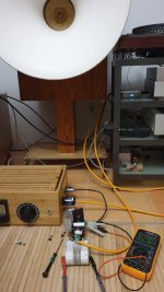
Thanks Felipe, tube rectification forever has been good sound quality and together with selenium rectification, were used in the field coil era. But not only, I suddently remembered this side effect is also necessary. Since then, I tame up the hit with the variac, aliviated lets me enjoy the SSHV2.
As for sound quality concerns, I am using an HV active diode bridge. It is same expensive than tube properly done. But I like it over for simplicity concerns. It comes with optimisation work, since SMD capacitors on the development board TEA2208DB1576, slighty slower down the performance. I haven't fully squeezed the juice out of it yet, and again I perfer it over more bulky ancient solutions.
Nowadays is a variety of slow down boards available for transformers.
Just avoid the even cheaper slow down modules for motors. I learned the hard way, these are different and cause damage to the diode bridge.
I have placed around Q1 the zener protections and diode SiC Cree. And a high power zener to output. Also is good performing BSP149 as Q2. It provides more heat to Q1, and a higher Vin Vout difference than before. 15V difference now. Is been a challenge, here is a powerful raw DC and then, a difficult load. Very grateful to all you, providing with knowleadge, choices and ideas.
Thanks,
Jordi
Thanks,
Jordi
Hi, Apologies if this has been asked and answered elsewhere, I searched around but couldnt find it..
Q: For a regulated output of 60 to 75V (adj), how to determine values for R9 and R10.
Thank you.
Q: For a regulated output of 60 to 75V (adj), how to determine values for R9 and R10.
Thank you.
Salas finally you will have to change the SSHV2 specs for less voltage & more current 🙂😉
N. B. Of course if it's stable.
N. B. Of course if it's stable.
Thanks and will do.Simply use half their normal value or bit below. 33k should work for the range you aim at.
Today I compared the sound of 4 different transistors for Q2 place.
The worst into my system (heavy load) goes to DN2540 although it has pleasant sound, seems not able to drive with strengh. Then 2ond place to the IXTP2N50 has a bit worse timbre, but already outside the speaker, more dinamic and alive. Following by IXTP1N100 would say a much great step, over those, with a convincing natural sound. The winner transistor is BSP149, not better timbre than 1N100 (not worse either, it is new and cold) but a far greater dinamic. The sound fills the room with an unexpected big sound, very much of my liking.
The worst into my system (heavy load) goes to DN2540 although it has pleasant sound, seems not able to drive with strengh. Then 2ond place to the IXTP2N50 has a bit worse timbre, but already outside the speaker, more dinamic and alive. Following by IXTP1N100 would say a much great step, over those, with a convincing natural sound. The winner transistor is BSP149, not better timbre than 1N100 (not worse either, it is new and cold) but a far greater dinamic. The sound fills the room with an unexpected big sound, very much of my liking.
Attachments
The Infineon BSP149 is hardly available in small quantity these days but we should keep its successful combination with IXTP in mind if the original Q1 Q2 DN2540N-5G will continue to be scarce in the future. Unfortunately that would also take a SOT-223 board modification.
As the board is now made, what TO-220 IXTP easier available combination worked best for you? So we can directly recommend for trying as Q1 Q2 substitutes in the cascode CCS?
As the board is now made, what TO-220 IXTP easier available combination worked best for you? So we can directly recommend for trying as Q1 Q2 substitutes in the cascode CCS?
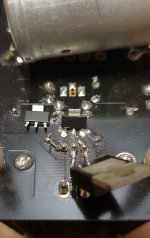
I placed the BSP149 on the Q2, by soldering from the PCB back side. Just after carefully split up the outside transistor pins a little bit as seen in the pic. atch.
Other than that, my preferred combination is Q1= IXTP02N50 / Q2 = IXTP01N100. But keeping in mind I have just an strong load to power the SSHV2. I may guess for loads 1-100mA can perform even better IXTP01N100 in both places.
Again not confirmed, because I got a weird clipping noise, can't handle 165mA.
I think @merlin el mago prefer this combination for a tube Plate load.
Felipe, if you are interested to give a try BSP149 on Q2, I have an spare to sent you and compare against 1N100.
Attachments
Last edited:

Thanks. By the way, clean the rework with isopropyl. So little current paths will not get a chance to be formed in the flux residue which is dust attractive.
For 100Vout R9 & R10 47K?Simply use half their normal value or bit below. 33k should work for the range you aim at.
Hi, need replacement for KSA1381, and find locally a BD140. I checked the voltages present, are around 40v there in a healty ksa1381 (reg. set at 80V.) So this 80V. PNP may work if there is no other concern?
Jordi
Jordi
Last edited:
- Home
- Amplifiers
- Power Supplies
- Simplistic mosFET HV Shunt Regs