I think at the expense of an additional board and if you have double secondaries (isolated) you can stack two regulators (in serial) to overcome the voltage limit.
Appreciate if you could show by a drawing as how to stack two regulators to get more than +540V with a DN2540 board please.
Thankyou.
Appreciate if you could show by a drawing as how to stack two regulators to get more than +540V with a DN2540 board please.
Thankyou.
Something like this:
Attachments
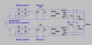
D9, D10 are 12V 1/2W zeners?
What will be the max. Vout?
CCS will be the sum of the two regs so max. 200mA?
What will be the max. Vout?
CCS will be the sum of the two regs so max. 200mA?
Last edited:
No, they are just diodes. The max reverse voltage should be more than half of the output.D9, D10 are 12V 1/2W zeners?
Theoretically - 2x400V=800V, but I'd give the layout 10-20% margin, so up to 700V approximately.What will be the max. Vout?
In a serial connection there is a sum of voltages, not currents, so the initial limit will apply.CCS will be the sum of the two regs so max. 200mA?
power diodes usually come in 200Vdc increments after 50V and 100vdc, then 200, 400, 600, 800 and just a few at 1000v and 1600v
What does the 1n4007 datasheet have to say?
Has anyone looked at worst case maximum output voltage yet?
Has anyone looked at worst case maximum output voltage yet?
1N4007 sounds good for me (1000V 1A).
The max voltage is hard to predict because of different filtering component. The very max would be the transformer's secondary voltage RMS without load multiplied by 1.414, but it is a very unlikely case.
The max voltage is hard to predict because of different filtering component. The very max would be the transformer's secondary voltage RMS without load multiplied by 1.414, but it is a very unlikely case.
Something like this:
I think that special care should be taken for the transformer : One of the winding beeing probably referenced to ground, the other one will be partly floating 800v above surrounding parts (core or other windings). Enamel insulation might not be sufficiant, you could then have arcing between windings or core.
Check if possible transformer specs, base insulation of 1000v should be needed. Specifically designed transformers is a solution to but more expensive.
Good point, but I can agree only partly.I think that special care should be taken for the transformer : One of the winding beeing probably referenced to ground, the other one will be partly floating 800v above surrounding parts (core or other windings). Enamel insulation might not be sufficiant, you could then have arcing between windings or core.
Check if possible transformer specs, base insulation of 1000v should be needed. Specifically designed transformers is a solution to but more expensive.
If a transformer has some voltage specifications it has to have strong enough insulation to sustain the tension. Even if the transformer is used in, say, full-wave rectification with the grounded midpoint the voltage difference between the outer part of windings is still twice the voltage across the single winding. So the enamel insulation must prevent arching by the design anyway for the case.
The case of the voltage difference between windings and the core is more interesting. I agree that there can be a problem. But if you are building a device with 600V supply you have to buy a transformer which can withstand the voltage (so - expensive). On the other hand if you take care of phase of the windings you can still ground the midpoint of one winding and then - there would be no point in the winding with double-high potential (relating to grounded core).
Last edited:
Even if the dielectric on a good trafo is usually good for this, a bifilar secondary should be avoided and a layer wound secondary with insulation layer to be prefered. Core should be grounded as usual. But this is nowhere an extreme case. Make it two trannys and your home free.
Last edited:
Good point, but I can agree only partly...
That was just to point out that some arrangement of transfo secondaries : windings in serie, heater's voltages referenced to a floating voltage , reflects internally by making neighbours sometimes big potentials differences separated by just a small fraction of a millimeter insulation.
As stajo told, quality transformer should not give any trouble, but better keep your ground connected to earth and a good differential breaker on the power line.
No.1N4007 sounds good for me (1000V 1A).
The max voltage is hard to predict because of different filtering component. The very max would be the transformer's secondary voltage RMS without load multiplied by 1.414, but it is a very unlikely case.
you must take account of the tolerance on Mains supply voltage.
Also the tolerance on the manufacturer's rated values.
Finally take account of the transformer regulation.
Adding these effects together one could get +50% above the rated secondary times sqrt(2).
If you have inductance in the PSU, then you must also add in the overshoot that is fairly common to this type of supply.
The main Safety test will be a primary to other parts HV check.Good point, but I can agree only partly.
If a transformer has some voltage specifications it has to have strong enough insulation to sustain the tension. Even if the transformer is used in, say, full-wave rectification with the grounded midpoint the voltage difference between the outer part of windings is still twice the voltage across the single winding. So the enamel insulation must prevent arching by the design anyway for the case.
The case of the voltage difference between windings and the core is more interesting. I agree that there can be a problem. But if you are building a device with 600V supply you have to buy a transformer which can withstand the voltage (so - expensive). On the other hand if you take care of phase of the windings you can still ground the midpoint of one winding and then - there would be no point in the winding with double-high potential (relating to grounded core).
I believe 1500V is a common test pass.
Few will do a Secondary to Secondary check.
Many "matched" windings are wound bifillar.
If both ends start at the same voltage then the far ends are at the same voltage. This results in ultra low wire to wire voltage.
But if the bifillar wires start at different voltages, then the wire to wire tension can become very large.
Last edited:
Transformer regulation was taken into account when I said "without load".No.
you must take account of the tolerance on Mains supply voltage.
Also the tolerance on the manufacturer's rated values.
Finally take account of the transformer regulation.
Adding these effects together one could get +50% above the rated secondary times sqrt(2).
If you have inductance in the PSU, then you must also add in the overshoot that is fairly common to this type of supply.
Taking into account inductance in the PSU automatically gives us some load and current, so it may be fifty-fifty.
As for the manufacturer tolerances... Well, 1000V is the working conditions, not pulse rating, but more important - the diodes are just some protection from short-circuiting the outputs and they are on the output of already limited by the regulators voltage. In case of the regulator problems there are a lot of parts that would gone and the diodes is the cheapest of them I think. Back to reality we are speaking of rather simple device (SSHV) and its simplicity are in the safety too - it was mentioned many times here in the thread.
Sorry for many mistakes in the previous message. English is not my mother tongue.
I'd like to add something. Slightly modifying the SSHV layout you can achieve a side but marvelous effect of isolating the transformer from the circuit by connecting the CCS backwards and moving it to the negative line in the lower SSHV. This way you won't have to ground any winding of the transformer (just frame and core).
I'd like to add something. Slightly modifying the SSHV layout you can achieve a side but marvelous effect of isolating the transformer from the circuit by connecting the CCS backwards and moving it to the negative line in the lower SSHV. This way you won't have to ground any winding of the transformer (just frame and core).
Hi Salas. I'm thinking of getting a couple of SSHV2 kits via the current GB that Tea-Bag is running; plan is to try them powering the driver stage of my valve amp...
Currently the driver stage power is sourced from the main CLCLC power supply. If I try the SSHV2 modules should I provide them with a separate transformer/rectifier or can I hook into the current supply, say at the terminals of the first cap (easiest due to screw terminals) or the rectifier?
Grateful for tapping into your wisdom, as always.
Ray
- Home
- Amplifiers
- Power Supplies
- Simplistic mosFET HV Shunt Regs