TO-92 may take the dissipation in this SSHV1 bias rather well -not in SSHV2-, 2SA1381 or KSA1381 for sure, its listed as SA1381 in German shops maybe because its printed so on its body if you look.
what kind of pot for SSHV2? Not used to these votage ratings. I plan to replace when all is tuned.
They won't work in high voltage ratings the pots, they are nested in low voltage areas. 0.5W Bourns multiturn will do.
Hi Guys,
I am about to build a SSHV1 clone.. already have the PCB, and carefully read through the first 2000 posts of this thread....
I've created a simple Excel spreadsheet to make "ballpark" calculations of critical resistors and Power dissipations easier.... I thought I'd share it with you guys , and try to save Salas some time...😉 as a way to say 'Thank You' for the great design and sharing it !
(Hopefully there's no mistake in the formulas 😀)
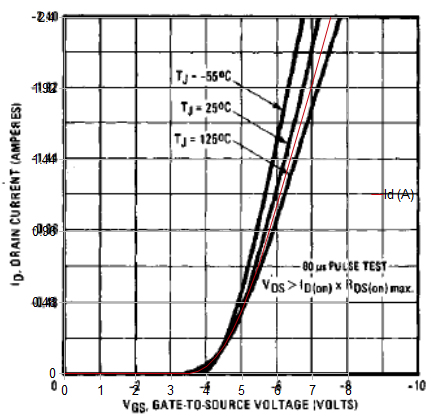
The CCS current resistor is calculated thanks to a very basic "Home Fitted" curve of the IRF9610. I've chosen an arbitrary intermediate junction temperature between 25 and 125 deg C. You're free to modify it to your needs and improve the Excel if you're a computer pro.
https://docs.google.com/open?id=0B4Rnva0idfhAMzlmOTRkODctMzNjNS00MTVmLTk1MGUtMGJjYTliMjkxNDcz
Last point: I'm using LibreOffice for editing, so I'm not sure if you guys will see the graphs correctly in MS Excel... (basically if you match the IRF datasheet graph with the Excel Graph, you should see the curves fit) PM me if the download doesn't work or if you have any questions.
Cheers,
Fred
I am about to build a SSHV1 clone.. already have the PCB, and carefully read through the first 2000 posts of this thread....
I've created a simple Excel spreadsheet to make "ballpark" calculations of critical resistors and Power dissipations easier.... I thought I'd share it with you guys , and try to save Salas some time...😉 as a way to say 'Thank You' for the great design and sharing it !
(Hopefully there's no mistake in the formulas 😀)
The CCS current resistor is calculated thanks to a very basic "Home Fitted" curve of the IRF9610. I've chosen an arbitrary intermediate junction temperature between 25 and 125 deg C. You're free to modify it to your needs and improve the Excel if you're a computer pro.
https://docs.google.com/open?id=0B4Rnva0idfhAMzlmOTRkODctMzNjNS00MTVmLTk1MGUtMGJjYTliMjkxNDcz
Last point: I'm using LibreOffice for editing, so I'm not sure if you guys will see the graphs correctly in MS Excel... (basically if you match the IRF datasheet graph with the Excel Graph, you should see the curves fit) PM me if the download doesn't work or if you have any questions.
Cheers,
Fred
Hi Fred
Its not easy to extract mA range from that International Rectifier published curve, has no much resolution down there, but from experience I would think that a 32.6 Ohm R1 may give more than 40mA in your example. ~50R I would say.
Its not easy to extract mA range from that International Rectifier published curve, has no much resolution down there, but from experience I would think that a 32.6 Ohm R1 may give more than 40mA in your example. ~50R I would say.
See the heatsink attached to the back of the amp. This is one We417 per channel ~160V @17mA, separate SSHV1 per channel, singlefeed OPT's (5k:32). The mosfets attach to the heatsink with tapped holes but the back panel of the case is inbetween the fet and the heatsink. Each CCS is running at 60 mA.
I added a layer of avvid heatsink compound between the sink and the case. This lowered the ouput mosfet temp to ~65C. Not quite 55C but not sure it is worth cutting the case to get direct mount to the sink ( I ran with the mofsets at 100c for quite, never thinking I wasn't getting good heat conduction.) The sink is plenty big at 3"Hx8"L with 22 x 1.5" fins) and runs about 28C. So I think I am done, sound is great.
Just received a set of the Jfets to start on SSHV2. It will be a compliment to and share the same external power supply, except this will run 41PL's @ 30mA also be a spud (single tube per channel) also this time I am trying out a parafeed config with smaller permalloy transformers.
For the SSHV2 based amp, should I wait on PCB's? The circuit looks simple enough and layout on perfboard should be straightfoward, I also like flexibility with cap selection and big precision resistors for the jfet, so leaning toward perboard instead of PCB, think this is a good decision or would performance with the PCB be signiiantly better?
An externally hosted image should be here but it was not working when we last tested it.
Hi Fred
Its not easy to extract mA range from that International Rectifier published curve, has no much resolution down there, but from experience I would think that a 32.6 Ohm R1 may give more than 40mA in your example. ~50R I would say.
Absolutely!
My model gives 51.8 Ohm for 40mA
The example here with 32.6 Ohm was for 60mA of CCS: The 40mA is the current that is shunt by Q3 on top of the current consumed by the load (it's not so clear in my spreadsheet, I'll make it more explicit for users here)
But you're totally right, the published picture is not so accurate (plus it's difficult to estimate the junction temperature), so the model should be used as a ballpark calculator only... then it's mostly up to what resistor you have in the drawers !
Here is the fitting I have on my LibreOffice spreadsheet 😎 (that is when IR curve is well aligned with the graph)
Here is the latest version of the file.
I've added comments and descriptions of what each cell does, and clarified the spreadsheet a bit.
https://docs.google.com/open?id=0B4Rnva0idfhANThlZWFiZTctYzI5Yi00ZjAxLWFlMWQtNWNhZGU5MzU0MmVj
Cheers
Fred
I've added comments and descriptions of what each cell does, and clarified the spreadsheet a bit.
https://docs.google.com/open?id=0B4Rnva0idfhANThlZWFiZTctYzI5Yi00ZjAxLWFlMWQtNWNhZGU5MzU0MmVj
Cheers
Fred
Absolutely!
My model gives 51.8 Ohm for 40mA
...
Here is the fitting I have on my LibreOffice spreadsheet 😎 (that is when IR curve is well aligned with the graph)
Bravo, that's a close one then. Nice effort and a handy tool to the user. Maybe I will have to stick it along the recommended schematic link.
Here is the latest version of the file.
I've added comments and descriptions of what each cell does, and clarified the spreadsheet a bit.
Even better for reading. Nice. But can you include the basic schematic without remote and big d1 so to be compatible with what most made?
Attachments
For the SSHV2 based amp, should I wait on PCB's? The circuit looks simple enough and layout on perfboard should be straightfoward, I also like flexibility with cap selection and big precision resistors for the jfet, so leaning toward perboard instead of PCB, think this is a good decision or would performance with the PCB be signiiantly better?
You try your own first since you are experienced enough I would say. We only very recently made some proto pcbs to test and know more soon.
Even better for reading. Nice. But can you include the basic schematic without remote and big d1 so to be compatible with what most made?
Sure !
Here is latest version :
https://docs.google.com/open?id=0B4Rnva0idfhAMzhiYThkNjMtZTZkYi00Njg5LWI0YmYtMTE1NGFlYTRiNjBk
And by the way, I will delete all obsolete versions of that file as I upload updates to avoid confusion.
Fred
Very nice. I will try it out more later and I can include V3 calc with the SSHV1 evolution post linked from page 1 for everybody to can point to and have less questions. With your permission of course. Is that OK?
P.S. With the last included schematic ''current reference'' cells should read ''LEDS Voltage'' D1,D2,D3 to match I think. You also include a rectification & pre-filtering drops calculation section. Would be better to depict that front end example with a schematic too, so people will picture it better?
P.S. With the last included schematic ''current reference'' cells should read ''LEDS Voltage'' D1,D2,D3 to match I think. You also include a rectification & pre-filtering drops calculation section. Would be better to depict that front end example with a schematic too, so people will picture it better?
- Home
- Amplifiers
- Power Supplies
- Simplistic mosFET HV Shunt Regs