[wiki=Main Page]return to diyAudio Wiki Main Page[/wiki]
[h=Introduction]%2[/h]
The SSDS (Simpler Simplistic Design by Salas) is a design by ....wait for it.....member Salas. 🙂
The board was designed by quanghao. This WIKI will attempt to provide instructions and/or guidelines to enable a properly working HV shunt reg as a result.
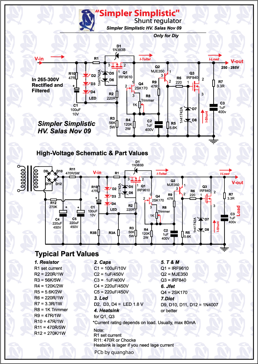
[h=Schematic]%2[/h]
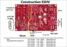
[h=Picture of a completed SSSSR (Salas Simpler Simplistic Shunt Reg)]%2[/h]

[h=Questions]%2[/h]
Question 1:
Am I supposed to use a transformer with CT? Because the PCB has a CT hole. (But the schematic shows no CT transformer)
Answer:
Populate only D10 and D12 and you can use a CT transformer. Leave D9 and D11 unpopulated.
If you use bridge rectifiers (for a transformer without CT), populate all D9 - D12, connect the 2 HV leads of the transformer to the 2 AC vias (the CT via should not be connected!). (Thanks member: housing)
width=100%|size=5|color=blue|color1=blue|color2=redQuestion 2:
Looking at the instructions, D1 is a 1N383B 150V 5A diode. Is this correct? I cannot find this component.
Answer:
In fact D1 is a 5 watt zener diode 1N5383B. It's there for protection of the IRF9610. (Thanks member: housing)
By the way. For some reason quanghao left this out.
width=100%|size=5|color=blue|color1=blue|color2=redQuestion 3:
Additionally, I am using the Solen Fastcap 1uF capacitors (630V) is this a good choice.
Answer:
They are perfect for the job.
width=100%|size=5|color=blue|color1=blue|color2=redQuestion 4:
What are the specs for the 1n41742A, I can't find a datasheet for it and it isn't sold in the USA
Answer:
Just any 12V half Watt or one Watt Zener you can easily get does the job fine.
width=100%|size=5|color=blue|color1=blue|color2=redQuestion 5:
How can I measure/test if the leds I got are the right ones for the job?
Answer:
With a 9V battery and 680R resistor, string 3 LEDs and measure the voltage drop across them 3. Choose a trio that drops 5.4-5.7V.
width=100%|size=5|color=blue|color1=blue|color2=red
[h=Suggestions/Tips]%2[/h]
Tip no. 1:
How much current should I set the shunt reg for.
The minimum is to allow +25mA on top of your load's consumption. That will take care of the internal needs of the reg and will keep its Zo to spec. If you have enough sinking, double the load's consumption + 25mA will give even better damping. For example if your circuit draws 30mA. Set for (30mA*2) +25mA. So set your circuit for 85mA.
Tip no. 2:
As pointed out by Dodo, the pads of the PCB are neither tinned or gold-plated. So it's wise to tin-plate the pads with a solder gun manually to prevent future oxidation of the copper pads whenever possible.(See picture) (Thanks member: housing)

Links:
The GB thread
[h=Introduction]%2[/h]
The SSDS (Simpler Simplistic Design by Salas) is a design by ....wait for it.....member Salas. 🙂
The board was designed by quanghao. This WIKI will attempt to provide instructions and/or guidelines to enable a properly working HV shunt reg as a result.
[h=Schematic]%2[/h]
[h=Picture of a completed SSSSR (Salas Simpler Simplistic Shunt Reg)]%2[/h]
[h=Questions]%2[/h]
Question 1:
Am I supposed to use a transformer with CT? Because the PCB has a CT hole. (But the schematic shows no CT transformer)
Answer:
Populate only D10 and D12 and you can use a CT transformer. Leave D9 and D11 unpopulated.
If you use bridge rectifiers (for a transformer without CT), populate all D9 - D12, connect the 2 HV leads of the transformer to the 2 AC vias (the CT via should not be connected!). (Thanks member: housing)
width=100%|size=5|color=blue|color1=blue|color2=redQuestion 2:
Looking at the instructions, D1 is a 1N383B 150V 5A diode. Is this correct? I cannot find this component.
Answer:
In fact D1 is a 5 watt zener diode 1N5383B. It's there for protection of the IRF9610. (Thanks member: housing)
By the way. For some reason quanghao left this out.
width=100%|size=5|color=blue|color1=blue|color2=redQuestion 3:
Additionally, I am using the Solen Fastcap 1uF capacitors (630V) is this a good choice.
Answer:
They are perfect for the job.
width=100%|size=5|color=blue|color1=blue|color2=redQuestion 4:
What are the specs for the 1n41742A, I can't find a datasheet for it and it isn't sold in the USA
Answer:
Just any 12V half Watt or one Watt Zener you can easily get does the job fine.
width=100%|size=5|color=blue|color1=blue|color2=redQuestion 5:
How can I measure/test if the leds I got are the right ones for the job?
Answer:
With a 9V battery and 680R resistor, string 3 LEDs and measure the voltage drop across them 3. Choose a trio that drops 5.4-5.7V.
width=100%|size=5|color=blue|color1=blue|color2=red
[h=Suggestions/Tips]%2[/h]
Tip no. 1:
How much current should I set the shunt reg for.
The minimum is to allow +25mA on top of your load's consumption. That will take care of the internal needs of the reg and will keep its Zo to spec. If you have enough sinking, double the load's consumption + 25mA will give even better damping. For example if your circuit draws 30mA. Set for (30mA*2) +25mA. So set your circuit for 85mA.
Tip no. 2:
As pointed out by Dodo, the pads of the PCB are neither tinned or gold-plated. So it's wise to tin-plate the pads with a solder gun manually to prevent future oxidation of the copper pads whenever possible.(See picture) (Thanks member: housing)
Links:
The GB thread
Attachments

Last edited: