Hi there,
Quite often, you need a very low power isolated supply: it could be for a panel meter, an add-on in an amplifier, an auxiliary supply, etc.
In such cases, the only viable option is to add a small 50/60Hz transformer, even though the power is ridiculously low.
Here is an alternative: it takes an existing supply, AC or DC, isolates it and converts it to the suitable level.
It is not regulated, the efficiency is low, but for power levels ranging from a few mW to a few hundreds mW, that is not really important.
A big advantage of such oscillators is that they are very undemanding, regarding the inductor/transformer in particular: this makes them DIY-friendly, to the point that even air-cored coils are usable when no other option is available (not something I recommend, but it is viable, as I will demonstrate).
These "oscilloconverters" have other advantages:
*because they operate in near-sinusoidal mode, at a stable frequency, their RFI footprint is relatively small.
*Unlike flyback converters, they tolerate a very loose coupling between primary and secondary, facilitating the construction and the insulation.
*The primary to secondary capacitance can be made extremely small, typically 5pF or less
*The transformer construction is extremely simple: a single two-wire primary and two-wire secondary is sufficient to obtain a main positive supply and an auxiliary negative one.
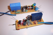
Here are two example of such converters, proofs-of-concept based on air-core coils.
One provides a shunt-regulated 18mA/15V output, and the other a 25mA/15V output. Both also provide a non-regulated negative output of -15 to -22V, 5mA maximum
Attachments
RFI is always a risk with an oscillator, although if it works in Class A (unlike most RF oscillators, which are Class C) you won't get much harmonic problems - apart from those produced by the rectifier. A toroidal core will reduce radiation at the fundamental frequency.
A nicely thought out idea.
I usually make an extra winding to solve a problem like this. Most toroidal transformers make it an easy option. 2 metres of wire often enough if not wanting more than a few VA. I fancy soft recovery diodes help with RFi. I don't like snubbers much. Not least the 4 x 10 nF caps often suggested. AM radio close to devices is a reasonable test.
This similar idea is still used. I realise Royer works against some of what you want. Just to say a variant. I built a Colpitts type circuit from a Royer as the ratios were possible. It was a circuit that shocking coils have shown on eBay. It was a 2N3055 connected to resonate where it liked. Was about 25 kHz. The 3055 was because that was what some show and I had some.
https://en.wikipedia.org/wiki/Royer_oscillator
Last edited:
If the frequency of the RFi happens to fall in the AM radio band. Often it does not. Fortunately an oscilloscope and a spectrum analyzer can help you find non-AM-band RFi.... help with RFi ... AM radio close to devices is a reasonable test.
Indeed.RFI is always a risk with an oscillator, although if it works in Class A (unlike most RF oscillators, which are Class C) you won't get much harmonic problems - apart from those produced by the rectifier. A toroidal core will reduce radiation at the fundamental frequency.
A lot depends on the transformer's construction: efficiency and radiation in particular.
Here, my point was to show what an absolutely minimalistic approach can achieve: the efficiency is ~50%, absolutely dismal even by the seventies standards, and the open, unshielded coil radiates a significant magnetic field in the immediate vicinity.
However, small air coils make incredibly inefficient radiators, and the effective radiated power as EM waves is absolutely minuscule, and in the far field, magnetic fields decrease as the cube of the distance.
Since the low frequency version operates at 1.1MHz, just in the AM band, I was able to make the test with a receiver: at 1m distance, the signal is loud and clear, at 1.5m it begins to fade, and at 2m it is just barely detectable.
Remarkably quiet in fact compared to a lot of modern gear.
Royer is an option, but probably more suited to higher power: it requires two active devices and two inductive components. It also tends to be remarkably quiet in general.A nicely thought out idea.
I usually make an extra winding to solve a problem like this. Most toroidal transformers make it an easy option. 2 metres of wire often enough if not wanting more than a few VA. I fancy soft recovery diodes help with RFi. I don't like snubbers much. Not least the 4 x 10 nF caps often suggested. AM radio close to devices is a reasonable test.
This similar idea is still used. I realise Royer works against some of what you want. Just to say a variant. I built a Colpitts type circuit from a Royer as the ratios were possible. It was a circuit that shocking coils have shown on eBay. It was a 2N3055 connected to resonate where it liked. Was about 25 kHz. The 3055 was because that was what some show and I had some.
https://en.wikipedia.org/wiki/Royer_oscillator
You are right, it could be a risk.Isn't there a risk for the gate at turn-on, caused by the positive puls via C3 ?
Mona
The way I generally use this oscillator is in combination with a capacitive supply, meaning the rise of the supply voltage is quite slow, but for a connection to a fast-start supply, a gate protection would be required.
I love the idea. It is nice to see something totally different and thought provoking come up.
Swaping the simple coil for a small toroid would assist a lot with EMI, and if you wanted to go fancy you could lash out with a semi or two more and probably get a more controlled frequency and perhaps more efficiency.
Love the idea.
Swaping the simple coil for a small toroid would assist a lot with EMI, and if you wanted to go fancy you could lash out with a semi or two more and probably get a more controlled frequency and perhaps more efficiency.
Love the idea.
Some additional details:
In these examples, the primary winding is made of 0.1 or 0.12mm wire.
Its DC resistance is about 8 ohm.
The primary is the inner winding, and the hot side (drain of the MOS) is the start.
The goal is to "bury" as much as possible the high-frequency/high-voltage turns, to minimize the emission of electrostatic field.
The primary to secondary insulation consist of two layers of heat-shrink tube.
This provides a good safety level in case it is needed, and reduces the primary to secondary capacitance.
Here, the total I-O capacitance (ground to ground) is about 5pF in one case, and 4.5pF in the other.
About 3pF of that is due to the windings.
A low capacitance is important, because it helps minimizing the parasitic common-mode current.
The secondary is made of 0.15mm or 0.2mm wire.
Ideally, the secondary should be arranged as a negative supply.
I will try to explain:
The rectifier at the output can be half-wave (a single diode), but it has to use the forward phase of the oscilloconverter: if a too important load is drawn from the flyback phase, the oscillator becomes unstable (chaotic).
For an auxiliary supply, it is acceptable, but the main output has to use the forward phase.
In order to make the secondary and primary turns facing each other as equipotential as possible, it is necessary to start with the cold side of the secondary (output ground) at the end side of the primary, and wind the secondary in the reverse direction. But, with a NMOS, this will result in a negative supply wrt to the secondary ground.
If no auxiliary negative supply is required, this has no importance, because the -DC output can become the ground: in AC, the + and - output are equipotential, but if a negative supply is required, the cold wire must actually be connected to the ground.
This could be mitigated by using a bifilar secondary, and would allow full power on both rails.
Anyway, even when the optimum configuration is not used, the common-mode disturbances are relatively gentle, about 5V at the oscillation frequency, from ground to ground, open circuit.
Since the transformer's capacitance is low, this translates in a low current, and even a small "Y" capacitance will be effective at attenuating this common-mode.
As I said, the efficiency for the air-cored versions is around 50%, both for the 1.1MHz and the 2MHz types.
Loss mechanisms differ somewhat according to frequency, but in the end, the result is more or less the same.
Improvements would be difficult without resorting to physically larger coils.
Replacing the plastic core with a generic ferrite cylinder increases the efficiency to about 70%.
With a suitable core shape and material, efficiencies in the 80% would be possible.
Going higher would be difficult, even with schottky rectified outputs: the Colpitts oscillator requires a series resistor R1 for its feedback, and this resistor will inevitably consume a certain amount of DC and AC power.
Using a choke instead would solve the issue, but it is probably not worth the trouble for such a small power.
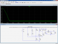
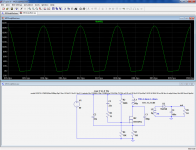
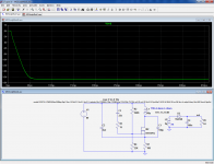
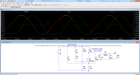
Note however that it is otherwise pretty optimal, and works in a ZVS/class E fashion: to illustrate this, here are the waveforms:
Green is the drain waveform, red the drain current, and yellow the inductor current, almost ideal.
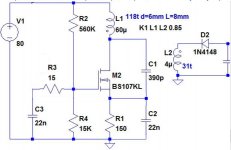
R3, in conjunction with the MOS input capacitance provides the phase shift for the optimum operation.
Attachments
Yes, it is, but I don't like it because the effective ground is now split between V+ and the "official" GND, meaning you have to rely on the supply's impedance to loop back the inductor current to the ground; no big deal at these frequencies, but as you can see from the waveforms, the current is 300mA^Isn't it more simple to do it this way ?
Talking about topological rearrangements, it is possible to redraw the Colpitts so that the oscilloconverter comes with a native, "natural" positive output for a N device.
It also avoids startup and split GND issues, but as there are no free lunches in engineering, there is is relative major drawback: now most of the components sit at an elevated HF potential, and will radiate an electrostatic field: the whole of C2, C3, R3, R4, R1, and a good part of M2, C1 and R2. That's quite a lot, and although electrically small capacitive antenna's aren't very effective either, they are much better than small inductive ones at these frequencies, meaning practically the whole of the circuit will have to be shielded... chose your evil...
It also avoids startup and split GND issues, but as there are no free lunches in engineering, there is is relative major drawback: now most of the components sit at an elevated HF potential, and will radiate an electrostatic field: the whole of C2, C3, R3, R4, R1, and a good part of M2, C1 and R2. That's quite a lot, and although electrically small capacitive antenna's aren't very effective either, they are much better than small inductive ones at these frequencies, meaning practically the whole of the circuit will have to be shielded... chose your evil...
Attachments
If the frequency of the RFi happens to fall in the AM radio band. Often it does not. Fortunately an oscilloscope and a spectrum analyzer can help you find non-AM-band RFi.
The problem I have is remembering to switch everything off when using a scope ( Eithernet over mains ). The radio is not bad. That fizzy sound says something is happening. I have never tried ferrite beads on my rectifier leads. It might be an idea.
Cheap, not very good shortwave radios seem to sell for £10 ( bought one for £2 from Superdrug ! ). Maybe they are useful. I have two spectrum analysers so do have the means. I just like simple ideas to share.
A word or two about component selection/scaling: after all, not everyone is going to need an 80V fed, 400mW format.
The tank components, L1, C1, C2 have to follow the √(L/C) law: if the supply voltage is increased for example, L should follow the √r rule, r being the ratio of the new supply voltage to the initial one, and C must follow the inverse rule, √1/r.
For a current increase, that's exactly the opposite.
Let's take an example: if I want to halve the output power to 200mW and keep the 80V supply, the current is halved meaning C=C0√0.5, and L=L0√2.
As I said earlier, the circuit has a good tolerance, and these rules do not need to be adhered to very strictly: in my examples, one is a 1MHz and the other is 2MHz, with a comparable power and supply voltage, yet the inductance has remained the same.
Resistor R1 is inversely proportional to the current, and there, it is advisable to be reasonably accurate.
C3 needs to be large enough, whatever.
The ratio of R2 to R4 must bias the MOS at the onset of its threshold for the nominal supply, and that's rather critical too, otherwise power will be wasted.
All the capacitors need to withstand 2.5x the supply voltage, and C1 needs to be COG/NPO or mica, PP, PS or similar.
These are mostly guidelines, extrapolated from a supposedly "reference" design, but for optimum performance, it is advisable to tweak the values thus obtained, because there are many interactions and second order effects at play.
Simulation is a good way to start, but the final circuit will have to be fine-tuned in reality.
If you use such a converter across a safety isolation barrier, be sure to respect all the precautions and distances required (which is not really difficult in this case)
Are there unseen advantages in the choke working as a load as in tube amplifers? On some tests I did on a similar ciruit the choke seemed to be swinging well above the rail. If useful can this be manipulated? I think I may have encouraged this by fitting a simple resistance serries current limiter.
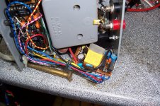
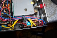
Here is an application illustrating the flexibility and small footprint of this PSU concept, a supply for a HF milliohmmeter.
The power requirements are relatively modest: +/-6.2V & +/-3V @50mA, and a battery supply should be possible, but not very practical: two 9V batteries could work, but would empty at an alarming rate and the other option, 2x6 AA elements is not very appealing.
Even a very small traditional 50Hz transformer would be difficult to lodge in such a cramped space, and the vicinity of the large galvanometer with its powerful magnet would make the coexistence tricky.
The primary power source is a capacitive supply, and the oscillator simply has a bifilar 10 turns secondary winding. Neat, cool and quiet.
Attachments
interesting,. one could use sectorial wound 3C20 gapped toroids for this (use triple isolated wire for good isolation). the secondary could be made resonant by arranging it as a doubler with 2 x 4.7nf and 1uH secondary, a 5818 schottky or bat54 can do the rectification. a capacitive preregulator is a good option , poor pf but who cares..
the colpitts is a class of oscillators that consist of an inverting gain element. to create the oscillation condition one needs reactive elements that give a 180 degrees phase shift. a 3rd oder network can do phase shifts more than 180 degrees, so a C-L-C pi (lowpass) network is connected between the output and input of the gain element. this version is called colpitts. a L-C-L network (highpass) is called hartley. there are various methods to draws the circuit and choose the ground connection, but they are all the same.
Sure, the performances depend greatly on the inductor's quality, and massive improvements on the internal efficiency can be gained: the I-V waveforms show that the oscillator is almost ideal class E.interesting,. one could use sectorial wound 3C20 gapped toroids for this (use triple isolated wire for good isolation).
However, the main goal of this project is to avoid traditional magnetics: ensuring good safety isolation standards with very small cores is extremely difficult, but here, with just a cylindrical construction, on an isolated ferrite rod, excellent isolation is possible in a small space, and unlike flyback topologies, this oscillator tolerates very loose primary to secondary coupling.
I am not too sure about that: a Colpitts requires a ring of 2 C's and 1 L, and if you put an additional tuned circuit coupled to the L through the mutual inductance, the results might be unpredictable.the secondary could be made resonant by arranging it as a doubler with 2 x 4.7nf and 1uH secondary, a 5818 schottky or bat54 can do the rectification.
If the coupling is very loose, and the tuning is exact, a good transfer of power over a significant distance will be possible, because the secondary will not interfere with the Colpitts, but it will be able to "siphon" power from it, that's the wireless power transmission principle, but this requires a very accurate tuning on both sides
It has a poor PF, but at least it is in the right direction (capacitive), and it helps damp transients present on the mainsa capacitive preregulator is a good option , poor pf but who cares..
Yes, I have chosen this particular implementation in order to minimize the electrostatic radiation of "hot" parts of the oscillator, essentially the drain of the MOS in this case.the colpitts is a class of oscillators that consist of an inverting gain element. to create the oscillation condition one needs reactive elements that give a 180 degrees phase shift. a 3rd oder network can do phase shifts more than 180 degrees, so a C-L-C pi (lowpass) network is connected between the output and input of the gain element. this version is called colpitts. a L-C-L network (highpass) is called hartley. there are various methods to draws the circuit and choose the ground connection, but they are all the same.
With a Colpitts, there is inevitably some power lost in the feedback resistor, but having a single two-terminal primary winding is an overwhelming advantage, especially for a flea circuit like this one.
One could use a choke instead, but I don't think the gain in efficiency is worth the trouble
- Status
- Not open for further replies.
- Home
- Amplifiers
- Power Supplies
- Simplistic Colpitts oscillators used as low-tech converters
