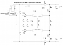
Based on the work of MrEvil and the alterations by PMI I would like to submit a simplified version of the capacitance multiplier circuit. I had suggested in another thread such a circuit would be an opportunity to incorporate the ability to cut-off the pass transistors during a fault condition and rather than pollute that thread It seemed appropriate to create this one.
Attached is the basis for the design of the capacitance multiplier, the shutdown circuit has not been decided upon yet. I'm thinking of using a simple two transistor latch to pull Q1 and Q4 base connections to ground when a fault event is detected. My initial notion is to use such facility in place of a relay on the amplifier output line for DC protection, but other possibilities exist like a low power standby mode, or shutting down for other faults like over temperature etc.
Ignore my choices for M1 and M2, these will likely end up being Fairchild FQP47P06 and FQP50N06 or similar low RDSon devices.
Any comments or ideas?
Attachments
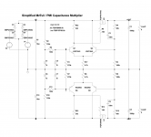
Why not split R11 into two series resistors, each resistor is 2K2, and connect the midpoint to a grounded bypass capacitor? This would keep some of the input ripple away from the gate of the pass transistor M1.
A constant current source would be even better, but at these voltages you can't use a standard JFET. You can, however, use a 100V rated Current Regulator Diode (like these from Mouser). Depending on load current, your diffamp's tail current is approx 3.7 mA, so an ideal CCS would be 1.87 mA. The Mouser product is 2.0 mA; after a little tweaking, it could be perfect.
A constant current source would be even better, but at these voltages you can't use a standard JFET. You can, however, use a 100V rated Current Regulator Diode (like these from Mouser). Depending on load current, your diffamp's tail current is approx 3.7 mA, so an ideal CCS would be 1.87 mA. The Mouser product is 2.0 mA; after a little tweaking, it could be perfect.
Hi,
Have you seen JLH's 1994 Ripple Eater article? Similar in some respects to what you are doing.
http://users.tpg.com.au/users/gerskine/greg/power supplies for electronic equipment.htm
These have been used successfully for the front ends of class A amps as well as many other applications.
Regards
Have you seen JLH's 1994 Ripple Eater article? Similar in some respects to what you are doing.
http://users.tpg.com.au/users/gerskine/greg/power supplies for electronic equipment.htm
These have been used successfully for the front ends of class A amps as well as many other applications.
Regards
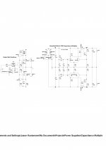
How about this? NE5534 max. power supply is 44V, so it can use for 35V power supply.
I'm sure it would be fine. I think I would prefer to remain with discrete components and doing so will allow a wider operating range. I will post back soon with some ideas on the shutdown circuit. The idea is to be as simple as possible while maintaining the essence of the Mr Evil design.
A constant current source would be even better, but at these voltages you can't use a standard JFET. You can, however, use a 100V rated Current Regulator Diode (like these from Mouser). Depending on load current, your diffamp's tail current is approx 3.7 mA, so an ideal CCS would be 1.87 mA. The Mouser product is 2.0 mA; after a little tweaking, it could be perfect.
That was also one of ideas PMI suggested. In fact, his pcb has additional holes for CRD for future implementation of the circuit at higher voltages.
Jason,
Have you built this simplified cap multiplier and can you report some of your experiences?
Have you built this simplified cap multiplier and can you report some of your experiences?
I have been working on a layout on and off, but I tend to be quite slow.
The project is still very much on my mind and seems to run well in simulation. I have even bought the pass MOSFETs I plan on using.
I'll be sure to post back when I have tested this.
The project is still very much on my mind and seems to run well in simulation. I have even bought the pass MOSFETs I plan on using.
I'll be sure to post back when I have tested this.
Been awhile...
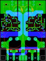
Well, I'm thinking on two possible versions. One Uber-simple, very small and another larger format Dee-luxe version. First will be the simple and small one.
I did this up dead-bug style and it works quite well in real life. The layout is the same size as my VSSA and the holes are on the same centres to allow one heat sink drilling to accommodate either an amplifier or a PSU.
Attachments
Can you produce the Zo vs Freq chart in LTSPICE for that circuit? Thanks.seems to run well in simulation.
Can you produce the Zo vs Freq chart in LTSPICE for that circuit? Thanks.
Can you make a suggestion as to how I should set that up? Guess I'm having a dense moment (Friday after a day's work, brain is fried).
Having a main voltage source on input and a current sink as output load, you got to right click on the sink, go to Small signal AC analysis section and set 1 for AC Amplitude. If you will run AC analysis and touch the probe (.params prb=0) on the output node you will get a chart (10Hz-1MHz is OK). Set the Y axis for logarithmic.
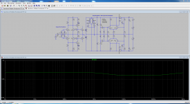
Not bad, the feedback keeps it low and flat enough. Could be somewhat worse in practice with real components but the shown trends should be representative.
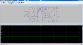
That's the output capacitor resonating with the inductive output impedance of the capacitance multiplier; the ESR provides damping. It's well worth simulating this with a realistic model of a capacitor.Here's something curious. Increasing the ESR (or inserting resistance) into the output capacitance really flattens out the curve.
- Home
- Amplifiers
- Power Supplies
- Simplified MrEvil / PMI Capacitance Multiplier