There is a point of diminishing return with respect to voltage losses. You could run it with more voltage dropped in the capacitance multiplier, at the expense of more heat in the pass MOSFET. So long as there is enough of a difference between input and output and the differential pair can drive the MOSFET gate to the required level, it should effectively perform the same no matter how much voltage it is dropping beyond the minimum for functionality.
A supply like this is geared towards projects like the VSSA - small to mid sized amplifiers with modest PSRR. Cleaner power can potentially benefit almost any design.
A supply like this is geared towards projects like the VSSA - small to mid sized amplifiers with modest PSRR. Cleaner power can potentially benefit almost any design.
So really the extra voltage drop would be a disadvantage considering the close proximity of the large capacitors and the shortened lifespan due to heat then.
In reality, playing music, the CM won't make too much heat.
It will have a standing dissipation in each MOSFET of only about 500mW, assuming a 250mA draw and a 2V drop-out. Worst case would be a large DC draw where it could have to stand 10-12W dissipation for what should be a short time. Hopefully such a fault condition triggers protection and / or causes a fuse to open long before such a situation becomes an issue.
Have a read back through the thread that Mr Evil and PMI were developing the concept >HERE<. There were concerns, but testing (and the PMI version in the wild) showed it to be a non-issue. Ask still4given, I know he has one or two of the PMI version.
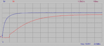
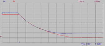
Another couple quick images. Turn-on and turn-off characteristics. The bulk supply 'hangs' because there is no bleeder resistor, just the drain that is provided my the CM circuit itself.
When turning on the supply will rise rapidly (there is a slope, it isn't instant) to the 3V mark as the CM input filter charges enough for the CM to become active, and then gives a gradual slope up to the target drop-out. Turn-on takes about 1s total.
When turning on the supply will rise rapidly (there is a slope, it isn't instant) to the 3V mark as the CM input filter charges enough for the CM to become active, and then gives a gradual slope up to the target drop-out. Turn-on takes about 1s total.
Attachments
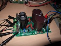
Current snapshot of where I'm at. I think it is just about time for a small order to validate the design. If all is well and there's interest I can arrange to place an order for a group buy.
Attachments


Hi Jason, looking good. Can you parallel the large caps to increase capacitance?.
Quan
There shouldn't be any need to, but there are extra tabs that can serve different functions.
1) To use dual rectifiers or
2) To add extra off-board capacitance or
3) To feed raw DC to something else
The intent is to be flexible and useful to many, though I'm sure it will not be everything to everyone. So far seems to work quite well. This one is sporting 80V parts and has been tested up to 65VDC so far.
When I get to the boosted rail PSU it will have parallel capacitors on the main rails.
I failed to mention that I have extra boards if anyone is interested. They are 2oz copper on FR4, double sided, plated holes with solder mask and silk screen. It might be nice to get some feedback or input from builders about what would improve it in the future. It will accommodate a fair range of devices and works well. Feel free to PM me if you want to give this PSU a try.
Ultimately I would like to be able to offer a nice generic CM PSU in a formal group buy.
As it stands now I have surplus from my initial order. There is no issue with the current boards, I just would like some feedback on what could be improved so when I reach the point where I'm ordering more they are the best possible. Sometimes it helps to have folks build and use a design to vaidate to overall approach. I have one assembled and parts for a second one on hand. So far it seems to work quite well, I'm happy with it.
As it stands now I have surplus from my initial order. There is no issue with the current boards, I just would like some feedback on what could be improved so when I reach the point where I'm ordering more they are the best possible. Sometimes it helps to have folks build and use a design to vaidate to overall approach. I have one assembled and parts for a second one on hand. So far it seems to work quite well, I'm happy with it.
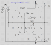
Any FET that will handle the full rail and pass the expected current with as low an Rds on spec as possible. For my build I chose FQA32N20C and FQA36P15 but that isn't carved in stone. Even the venerable IRFP240 and IRFP9240 or IRFP140 and IRFP9140 should work fine. There's nothing special about them. Even bipolar darlingtons transistors could be used (works in sim and I plan on trying with TIP142 and TIP147 myself).
Jason, can you measure the screw hole heights from the board for your rectifiers and outputs? Are you using M3 hardware?
Hi pinnocchio,
I have some spares of this board. How about $12 plus postage? PM me if you are interested in a board.
I have some spares of this board. How about $12 plus postage? PM me if you are interested in a board.
Jason, can you measure the screw hole heights from the board for your rectifiers and outputs? Are you using M3 hardware?
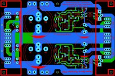
My rectifiers are mounded pretty low and have the holes about 0.400" above the board. I think giving a little more latitude, say 0.500" might be better for those. The mounting holes for the outputs are more generous at about 1.000" off the board.
- Home
- Amplifiers
- Power Supplies
- Simplified MrEvil / PMI Capacitance Multiplier