Hi folks
I built a DAC and it works well, but I think the cheap Chinese diamond buffer board I fitted as an analogue output stage is the weak link and want to replace it. I think it's a good design, looks to be copied from a Walt Jung design, but the components are all fake imho, it has 8 transistors that I am sure will be fakes and the transistors are Elna Silmic and Panasonic FC so I reckon those are fake too.
Anyways, to replace it I' like to use a B1 buffer, but there simply isn't room to fit it in, so I was thinking about how small I could make a modified B1 buffer.
Looking around the forum, I found a simplified B1 schematic and fiddled with it a bit to produce the layout below.

Have I butchered the B1 or will this modification work? I kept the original component values, maybe some of those need to be changed. I'm going to use 4x BF862 trannies instead of 2Sk170s,so should I reduce the input from 18v to 15v? I expect some resistor values will have to be changed too.
Nelson Pass wrote this about using Bf862s in the B1:
Some other notes I found on the forum:
Be mindful of 2 things using the BF862
I built a DAC and it works well, but I think the cheap Chinese diamond buffer board I fitted as an analogue output stage is the weak link and want to replace it. I think it's a good design, looks to be copied from a Walt Jung design, but the components are all fake imho, it has 8 transistors that I am sure will be fakes and the transistors are Elna Silmic and Panasonic FC so I reckon those are fake too.
Anyways, to replace it I' like to use a B1 buffer, but there simply isn't room to fit it in, so I was thinking about how small I could make a modified B1 buffer.
Looking around the forum, I found a simplified B1 schematic and fiddled with it a bit to produce the layout below.
Have I butchered the B1 or will this modification work? I kept the original component values, maybe some of those need to be changed. I'm going to use 4x BF862 trannies instead of 2Sk170s,so should I reduce the input from 18v to 15v? I expect some resistor values will have to be changed too.
Nelson Pass wrote this about using Bf862s in the B1:
BF862 is a great part, but it cannot be used in B1 without some adaptations in schematic. In B1 JFETs are running at Idss and dissipation will be a problem - up to Id of 10mA will be OK
Some other notes I found on the forum:
Be mindful of 2 things using the BF862
1) you must use gate stopper resistor OR ferrite bead on the gate lead. The intended purpose of the BF862 was RF.
2) Idss runs high and the devices run warm. A TO92 transistor will dissipate heat through its legs, for the BF862 the PCB trace thickness should be mindful of the added purpose of dissipating heat.
If you are using an SMT adapter, use a 100R resistor instead of wire for the gate lead.
Attachments
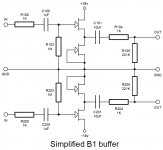
The bottom part needs to be powered by +18 volts, not minus. B1 uses asymetrical power.
You can build B2 with symetrical powe supply or mesmerize B1 without caps.
As shown, it could use some dc volts on gates, may be even some drain resistors to limit the current.
You can build B2 with symetrical powe supply or mesmerize B1 without caps.
As shown, it could use some dc volts on gates, may be even some drain resistors to limit the current.
Thanks for the feedback.
I wasn't aware there was a B2 or a mesmerize version, I shall have to look those up and study, cheers.
I'll try to modify my schematic to take account of your points.
I wasn't aware there was a B2 or a mesmerize version, I shall have to look those up and study, cheers.
I'll try to modify my schematic to take account of your points.
- Status
- Not open for further replies.