I was searching for uses for LM317 in a high voltage regulator (for a tube preamp or headphone amp) and came across something interesting in John Broskie's blog where he introduced his PS-1 regulated power supply.
PS-1 Solid-State Regulator Kit
This is what caught my attention:
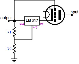
I understand that a MOSFET pass element will give far superior performance, but what if I want to use something super simple and durable to get about 300VDC at 40mA?
There are some common power pentodes that when triode-strapped will work with 90V to 100V plate-cathode, with grid-cathode voltage of 5V to 10V. That would provide enough voltage between the IN and OUT pins of the LM317 (or TL783). Likely tube choices would be EL86, 6P3S (the cheaper version), or 6AV5GT. 6AS7 or 6080 would also work, of course. (6V6 or EL84 won't give enough Vg-k for the LM317 to work.)
- Will the LM317 survive this? The pass tube should warm up slowly, which should keep too high a voltage from appearing between the IN and OUT pins of the LM317 -- right? Or am I wrong about that?
- Would a tube rectified B+ solve the problem? It would mean another voltage drop. It would be nice to be able to get a regulated +300V from a raw B+ of +450V.
I suspect that if this type of regulator was any good it would have been used by now. What am I missing?
--
PS-1 Solid-State Regulator Kit
This is what caught my attention:
I understand that a MOSFET pass element will give far superior performance, but what if I want to use something super simple and durable to get about 300VDC at 40mA?
There are some common power pentodes that when triode-strapped will work with 90V to 100V plate-cathode, with grid-cathode voltage of 5V to 10V. That would provide enough voltage between the IN and OUT pins of the LM317 (or TL783). Likely tube choices would be EL86, 6P3S (the cheaper version), or 6AV5GT. 6AS7 or 6080 would also work, of course. (6V6 or EL84 won't give enough Vg-k for the LM317 to work.)
- Will the LM317 survive this? The pass tube should warm up slowly, which should keep too high a voltage from appearing between the IN and OUT pins of the LM317 -- right? Or am I wrong about that?
- Would a tube rectified B+ solve the problem? It would mean another voltage drop. It would be nice to be able to get a regulated +300V from a raw B+ of +450V.
I suspect that if this type of regulator was any good it would have been used by now. What am I missing?
--
I suspect that if this type of regulator was any good it would have been used by now.
That's a conceptual circuit, a practical one would have additional diodes, capacitors, resistors, etc.
TI has a HV regulator app note. Audio Research and others have used a tube series regulator,
based on tubes like the 6550 and 6080.
Last edited:
OK, that is true that it's a conceptual circuit.
A tube series regulator would need a tube error amplifier, which means another cathode to heater voltage limitation that can't be violated. That could mean two separate heater supplies would be needed, one for the pass tube and the other for the error amplifier tube.
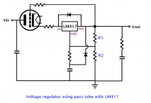
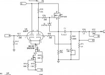
How about if the suggested protection diodes, etc. were in place? Something like the attached...
A tube series regulator would need a tube error amplifier, which means another cathode to heater voltage limitation that can't be violated. That could mean two separate heater supplies would be needed, one for the pass tube and the other for the error amplifier tube.
How about if the suggested protection diodes, etc. were in place? Something like the attached...
Attachments
How about if the suggested protection diodes, etc. were in place? Something like the attached...
That's more like it, but these kinds of circuits take some development before they will work reliably.
Usually there's a compensation cap across R1.
Last edited:
Usually there's a compensation cap across R1.
Looking at the various Maida-style regulators I've seen, there's often a diode across R1, but not a cap. Here's a link to the original Maida application note:
http://www.ti.com/lit/an/snoa648/snoa648.pdf
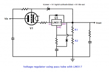
Here's a more fleshed out conceptual schematic (attached).
Here's a schematic of a 2000VDC regulator using a pass tube and an LM317. It's attributed to Jim Williams, who I think was the founder of Linear Systems.
An externally hosted image should be here but it was not working when we last tested it.
I'm not sure if that's a working circuit or not. If it's capable of delivering 2000VDC, I'm sure it could be scaled down to provide 350VDC.
So, does that mean this is a viable idea for a simple circuit? What I find attractive about it is that it gives me a use for a couple of 6AV5GT tubes I have on hand that I won't have a use for otherwise.
--
Attachments
Here's a schematic of a 2000VDC regulator using a pass tube and an LM317.
It's attributed to Jim Williams, who I think was the founder of Linear Systems.
If Jim Williams designed that, I'd definitely go with it, carefully adapted.
Remember the load must drain a certain minimum current for the Zener.
You may need an extra load resistor to establish that.
Last edited:
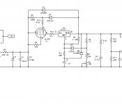
Here’s a regulator I built using a 6L6GC tube works marvelously. One of the best
power supplies I’ve ever built.
Looks good, do you use it for a preamp, or for an output tube screen regulator?
Looks good, do you use it for a preamp, or for an output tube screen regulator?
I’m using it in a line stage. I was really surprised how quiet
It is!!
I’m using it in a line stage. I was really surprised how quiet It is!!
Can you post the schematic for the whole thing? How much gain does the line stage have?
In some regulator circuits, the output capacitors (if not sized right) can cause noise peaking.
Last edited:
OK, that is true that it's a conceptual circuit.
A tube series regulator would need a tube error amplifier, which means another cathode to heater voltage limitation that can't be violated. That could mean two separate heater supplies would be needed, one for the pass tube and the other for the error amplifier tube.
How about if the suggested protection diodes, etc. were in place? Something like the attached...
I’ve tried running this thru spice using a 6080 tube, it doesn’t simulate well, but
Could be just a glitch or poor spice model.
Can you post the schematic for the whole thing? How much gain does the line stage have?
In some circuits output capacitors, if not sized right, can cause noise peaking.
Sure
Attachments
Sure
Is the variable resistor the volume control?
Is the variable resistor the volume control?
It adjusts the amount of feedback to set the gain for the stage.
But I’ll have to lower the 280K resistor to about 47k to really lower the gain.
I’m looking to adjust the gain from about 10dB to about 18dB.
This will help it mate with many different amplifiers.
The 5.6uF output coupling capacitor C1 is within the feedback loop, so it's pretty large.
I've had good results with only 1uF in similar circuits. Do you want to drive low input
impedance amps?
I’m looking to adjust the gain from about 10dB to about 18dB.
Counting on thumbs: single straight 6SN7 gives gain about 14. Used as a pair this way, about half, say 7. Gain of 7 is 17dB. Your low plate resistor may give less. So you may not get 18dB, though you could get close, with _no_ NFB applied.
- Status
- This old topic is closed. If you want to reopen this topic, contact a moderator using the "Report Post" button.
- Home
- Amplifiers
- Power Supplies
- Simplest possible tube regulator -- will it work?