Nah. That's too much work. It's much better to let us guess and shoot us down when we guess wrong... 🙂
Tom
Tom
The Socratic method. A pleasure always.
I did a trick somewhat like that quite a while back, just using a rail to rail op amp.
Power supply voltages for the op amp set the clipping point.
It was in a control loop to set the output current saturation level.
Not passive though.
I did a trick somewhat like that quite a while back, just using a rail to rail op amp.
Power supply voltages for the op amp set the clipping point.
It was in a control loop to set the output current saturation level.
Not passive though.
Last edited:
But the whole concept is still not clear. The only thing I can make of it is that you want to make a 'sliding-slope' limiter, from a transistor and a zener (only, with help from some component-friends), passive and with extreme wide range covering both dc and ac.
I don't know what this device would be called, but if I were going to name it, it would be a "pass-thru voltage limiter". It is different from a voltage regulator, because a regulator generally means it maintains a steady set voltage. EXAMPLE: you want 1.5 VDC max. a normal voltage regulator will take a somewhat variable input voltage and produce a stable 1.5 VDC.
What I am looking for is something that will accept a range of voltage, that can be 0V up to some maximum value, where it will allow the voltage below the max value to pass-thru as-is, but when the max value is reached it will not pass more than the maximum. Another way to say it is the circuit should do nothing until the set voltage limit is reached, at which point it then limits the voltage to the limit and continues to allow current to pass thru.
So because the incoming voltage is not constant or knowable, something like a voltage divider wouldn't work (or I'd just go with that).
What is, just to inquire, your 'electronics knowledge level'?
I think there is a familiarity with working principles and then there is knowledge of practical application. I have a decent understanding of the working principles but because I do not regularly design or build circuits I do not have much in the way of practical experience.
"if I were going to name it, it would be a "pass-thru voltage limiter"."
Most would just call that a clipping (or clamping) circuit.
Most would just call that a clipping (or clamping) circuit.
Last edited:
What is the voltage at (1) referenced to?
It's the voltage of the DC source, so whatever the DC source voltage is, (1) should be roughly the same as long as it is below the zener voltage.
If Vs is greater than the zener voltage and (2) is taken to a potential below the negative terminal on Vs, all you'll get out of that is Vs-Vz, where Vz is the zener voltage. If you pull more current than the zener can handle you blow the zener.
Right, the zener will limit the voltage to its zener voltage. That's what I wanted, because at that point I have a known voltage value to work with and that can be adjusted with a more traditional regulator or a divider.
Ok, so assuming that worked you now have a circuit that either consumes gobs of power (and blows the zener) or has high output impedance. Is that what you want?
So as long as it has some kind of load or resistance on the outputs, it will work? Or would it need a resistor somewhere along the line?
As pointed out above, I don't see a way to get the transistor to conduct as it's reverse biased. Unless Vs can be negative that is. If it was to conduct it'll blow instantly as it would short out Vs.
You mean because the emitter of is connected to the the source without anything in between? How can this be prevented without lowering the total voltage of the circuit by sticking a resistor in there? How about this: both (1) and (2) are connected to the (+) side of a load, and the emitter is connected to the (-) side?
Unless I'm missing something fundamental I'm just not seeing a) how this circuit would work as a limiter and b) how it would even work without blowing up. Hence, my comment earlier that it's fundamentally broken. But then again, you're leaving a lot up to the imagination here. What are the voltages at (1) and (2) referenced to? Can Vs be negative?
The zener provides a limiting function of sorts by virtue of not allowing current to flow until the voltage meets its zener voltage. That is why (2) is the limited output, which can have additional components included if need be to make it work. The diagram I drew is just the foundation that I came up with to represent the idea that I had. Voltage (1) would be the pass-thru voltage that should not be touched, and would be below the user-set limit voltage.
Example with zener voltage at 3.3V and 1.0V on the circuit:
Voltage is 1.0V then (1) should be 1.0V and (2) will be open circuit so 0V
Voltage is 5V then (2) will be closed, (1) open and (2) should be 3.3V.
A shunt regulator can be a limiter. Here's one example:
View attachment 1152971
If the input voltage is below Vz+Vbe you get the input voltage across RL. Once the input voltage exceeds Vz+Vbe Q1 will conduct and limit the voltage across the load. I would add a resistor in series with the base to limit the base current.
Tom
That may be a solution, but it looks like none of these will work at the millivolt level.

I was literally going to move up from zener to opamp before you posted this. lol Searching for "clipper circuits" yields the kind of results I was aiming for...and hey, I did not see that schematic until you shared the link - it is curiously similar to the idea that I came up with with the addition of a few resistors here and there.
Not obvious how to make it into a bilateral clipper, though.
Accuracy of mV requires an op amp feedback circuit.
Accuracy of mV requires an op amp feedback circuit.
@rayma The concept of a voltage follower seems interesting, and may be applicable here too.
Also, I found this:
https://www.electronics-lab.com/article/diode-clipping-circuits/
Scroll to the end and they show a clipper that uses zener diodes, but for an AC power source. I think that I was rather spot-on with my approach considering that I was trying to make it work with DC, and that people with higher levels of electronics experience should have been able to run with this without directing condescension my way. I mean, my expertise is programming and if you give me a workable-yet-vague description of what you want a program to do, I can probably figure it out and tell you if it can work and how to make it work without shitting on you for not getting the lingo right or airing a generally snobbish "you should already be an expert before you ask any questions" type of attitude.
But oh-well, not going to dwell on that. I will see what can be done to make these work on the millivolt scale. I was kicking around the idea of amplifying the millivolt voltage with an opamp, then using the amplified voltage to determine whether the base/reference voltage should be allowed to pass. And yes, I realize that will require external power but I just don't see off-the-shelf components working with millivolt precision passively. Maybe someone knows something tho...
And do not transition sharply.
This could actually preferable in some cases, and the overarching point being that zeners or diodes in general can be used to make this kind of a circuit.
Also not terribly precise. Then you'll be battling device variation between opamps (assuming you build more than one circuit), asymmetric clipping, etc. The saturation voltage of the opamp is not a controlled variable. It'll depend on process, temperature, and voltage. So there goes the mV precision out the window. Even if it was controlled, you'd still be left with the precision of the supply voltage (or lack thereof).I did a trick somewhat like that quite a while back, just using a rail to rail op amp.
Power supply voltages for the op amp set the clipping point.
It was in a control loop to set the output current saturation level.
Not passive though.
Tom
The DC voltage source has two pins. Which one is the reference for terminals (1) and (2)? If (1) and (2) are referenced to ground, where is ground in this circuit?It's the voltage of the DC source, so whatever the DC source voltage is, (1) should be roughly the same as long as it is below the zener voltage.
You actually don't have a known voltage. You have a voltage that's known to within ±5% and that depends on temperature and also the current through the zener. You won't get the mV precision you desire.Right, the zener will limit the voltage to its zener voltage. That's what I wanted, because at that point I have a known voltage value to work with and that can be adjusted with a more traditional regulator or a divider.
You would need to limit the current through the zener to prevent it from blowing. Whether you choose to do that by adding resistance in series with the zener (which now becomes the output impedance of the circuit) or by imposing restrictions on the load resistance is up to you.So as long as it has some kind of load or resistance on the outputs, it will work? Or would it need a resistor somewhere along the line?
No. Because Vce is negative.You mean because the emitter of is connected to the the source without anything in between?
There's no load drawn in your schematic.How can this be prevented without lowering the total voltage of the circuit by sticking a resistor in there? How about this: both (1) and (2) are connected to the (+) side of a load, and the emitter is connected to the (-) side?
That's great. Further develop this into an actual circuit. Then simulate it in spice or whatever circuit simulator you prefer.The diagram I drew is just the foundation that I came up with to represent the idea that I had.
I have no idea what that means.Voltage (1) would be the pass-thru voltage that should not be touched, and would be below the user-set limit voltage.
Example with zener voltage at 3.3V and 1.0V on the circuit:
Voltage is 1.0V then (1) should be 1.0V and (2) will be open circuit so 0V
Voltage is 5V then (2) will be closed, (1) open and (2) should be 3.3V.
DING! DING! DING!!!!That may be a solution, but it looks like none of these will work at the millivolt level.
I suggest that you re-read what I wrote in Post #4. You could also look at how sine shapers work. That's not too different from what you're doing. You were also given some good info in Post #14. Look up that patent. Pat2pdf will come in handy: www.pat2pdf.org
Tom
I've made a 12V voltage regulator for my motor bike years ago with such a function. The led turnlights went beserk above 12.6V but in stationairy the battery (a very large cap actually) was only a 8V, which was ok for the leds.What I am looking for is something that will accept a range of voltage, that can be 0V up to some maximum value, where it will allow the voltage below the max value to pass-thru as-is, but when the max value is reached it will not pass more than the maximum. Another way to say it is the circuit should do nothing until the set voltage limit is reached, at which point it then limits the voltage to the limit and continues to allow current to pass thru.
So the idea is not strange, even possible, but it requires neccessary definitions, environmental borders, specifications and a formal goal to achieve.
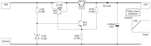
It would be ideal if your 'set voltage limit' is 'sliding along with the input signal' to get an expanded limiting range well over the commonly used circuits. Just as if the 5.6V zener in the attached picture of the Autodrop regulator is not really fixed (an 'anchored' reference), but is altered dynamicly by the outward circumstances.
Doable! I still doubt passive only.
Attachments
@tomchr @Citizen124032 After some trial and error I was able to get it to work the way I wanted to using the diode clipper circuit and some real non-chinesium germanium diodes (1N34A). It was pretty simple after all. The 1N34A diodes will conduct around 0.1V and will drop the voltage by 0.3V, so you can stack them up to get the target voltage down in ~0.3V increments. I think it could be further improved using opamps but for my purposes it is good enough as it is now.
It'll still be temperature dependent and not programmable in NN mV steps, but whatever. If it suits your needs, great.
Tom
Tom
We're all curious about the realised circuit...
Refer to post #29 and check the link I posted for more info about diode clipper circuits and how to make one.
- Home
- General Interest
- Everything Else
- Simplest 0 mV to NN mV Voltage Limiter