I need to take about .2 dc volts and increase it to about 5 volts. Is there a simple circuit to achieve this? The voltage is supplied when a piezo transducer is struck and the amp can not produce any voltage when it is not being struck. I googled it, but I ended up more confused than when I started. THIS looks promising, but it starts with a voltage of .7.
Please let me know if you have any ideas on this.
Thanks
Jeremy
Please let me know if you have any ideas on this.
Thanks
Jeremy
Waaaaaaaaa?
Do you need a DC/DC converter or an amplifier? They are two different things.
An amplifier is a powered device that can take your 0.2V and amplify it to 5V.
A DC/DC converter would (in theory) take the 0.2V and boost it to 5V. That's not going to happen though.
Do you need a DC/DC converter or an amplifier? They are two different things.
An amplifier is a powered device that can take your 0.2V and amplify it to 5V.
A DC/DC converter would (in theory) take the 0.2V and boost it to 5V. That's not going to happen though.
Jeremy
It will be better if you describe exactly what you want to achieve. Is it really a dc amplifier or are you amplifiying the signal from the piezo transducer? Or is it just a circuit which switches between two output voltages?
It will be better if you describe exactly what you want to achieve. Is it really a dc amplifier or are you amplifiying the signal from the piezo transducer? Or is it just a circuit which switches between two output voltages?
You could use an op amp as amplifier, e. g. like here on page 2, figure 2. R1 = 270 Ohm, R2 = 6,8 kOhm could give you the gain you want.
Doesn't seem like it will work with R3. Actually most of the parts in your circuit, athough fine by themselves, don't make too much sense together. Once you fix your circuit a bit a darlington may provide the missing brighness.
analog_sa said:Doesn't seem like it will work with R3. Actually most of the parts in your circuit, athough fine by themselves, don't make too much sense together. Once you fix your circuit a bit a darlington may provide the missing brighness.
Can you give me some tips on how to improve it? It actually does work pretty well, like I said except for the brightness, but I would like to learn about what I am doing instead of just using bits of different circuits I find and piecing them together. Should I get rid of R3?
Thanks
Jman
If it works very well then your circuit is wrong as it shows the led getting current through a 1M resistor.
I'm sure you are right, can you expound on what you are getting at. Obviously I don't know what I am doing or I wouldn't be having problems with a circuit that only has five parts. So rather than making comments about what I'm doing wrong, please help me make a circuit that will work. I don't mean to be rude, but if I had the answers I wouldn't be asking you to help.
If you don't want to help, I understand, but It doesn't do me any good for you to make comments that make no sense to an average guy like me trying to get an understanding of what I am doing.
I really mean no offense, but I just don't have the knowledge that it takes to understand your reasoning.
Jman
Use Ohm's law and do the math. I=U/R.
How much current can flow through a 1M resistor, when you have 9 V? Compare that to the forward current of your LED.
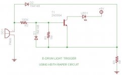
If you look at the article you will see that you forgot a GND connection at the transistors lower leg. D2 and R3 are left over from an OR circuit that you only need, if you want two or more transducers to switch the same LED. Use the second schematic from the article, i. e. delete D2 and replace R3 with a jumper.
The LED is drawn the wrong way round in your schematic. The arrow shows the current flow, which is from + to -.
How much current can flow through a 1M resistor, when you have 9 V? Compare that to the forward current of your LED.
If you look at the article you will see that you forgot a GND connection at the transistors lower leg. D2 and R3 are left over from an OR circuit that you only need, if you want two or more transducers to switch the same LED. Use the second schematic from the article, i. e. delete D2 and replace R3 with a jumper.
The LED is drawn the wrong way round in your schematic. The arrow shows the current flow, which is from + to -.
Now that I can understand!😀 Thank you very much Pacificblue. That is a very helpful answer that I learned from and got some very useful info!!! I really appreciate your time in looking at this for me.
I will let you know how it works out.
Jeremy
Here is the updated schematic. much easier actually!😀
I will let you know how it works out.
Jeremy
Here is the updated schematic. much easier actually!😀
Attachments

Significant improvement. What is the purpose of R2 and D1? Consider using a second transistor in a darlington connection.
Thank you analog, I will definitely take that into consideration. I don't know the purpose of those components. They were in the original schematic that I got the switch idea from. I was just guessing that they somehow affected the sensitivity, but I really don't know. This is another idea I got from someone on another forum that I am going to try also. Schematic
R1 and R2 set the bias point. D1 has a protective function.analog_sa said:What is the purpose of R2 and D1?
To drive a single LED?analog_sa said:Consider using a second transistor in a darlington connection.
R2 - bias point? You mean it limits the input voltage so as not to overbias the transistor? 🙂 Protective function? How much EMF can a piezo possibly generate? If anything needs protection it's the poor led when a real man hits the drum.
jman 31 said:They were in the original schematic that I got the switch idea from.
Actually there is no 100k resistor in series with the input in that circuit but there is a current limiting resistor in series with the LED. If you build the circuit as shown it will work better than yours although the output of the piezo may not be sufficient and the input impedance is probably too low. A fet or a darlington should work fine.
Thanks for the tips. I will continue this project tomorrow and I hopefully with the ideas I've received from you guys, I will have success!
Don't forget to provide some forward bias for the transistor. I think the easiest solution is to use a FET. It will
analog_sa said:If anything needs protection it's the poor led when a real man hits the drum.
jman 31 said:The led has a built in resistor to handle the voltage although that is not shown on the schematic.
Yes, there is. See link in post #11.analog_sa said:Actually there is no 100k resistor in series with the input in that circuit
That would indeed be more promising, butanalog_sa said:I think the easiest solution is to use a FET.
jman 31 said:It actually does work pretty well, like I said except for the brightness
- Status
- Not open for further replies.
- Home
- Amplifiers
- Chip Amps
- Simple voltage amp?