Stop oscillations by putting a small ferrite ring over each lead right up at the valve holder tag. Ground the cathode and put the meter in the anode side.
Look here and pick the best bits to suit: https://valveheaven.com/wp-content/uploads/2015/03/An-inexpensive-easy-to-build-diy-valve-tester.pdf
Look here and pick the best bits to suit: https://valveheaven.com/wp-content/uploads/2015/03/An-inexpensive-easy-to-build-diy-valve-tester.pdf
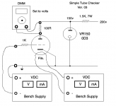
So you want to generate the negative voltage between the cathode and ground? Thats a smart move, as it allows direct measurement of grid current over the 100K grid resistor using a 10Meg input impedance voltmeter.
The downside is that your supply needs to be able to sink current, what you can do, is shunt the supply with a 200mA CCS (LM317 CCS) for example.
Ive build approx 4 tube testers so far, but most have become to heavy for daily use. Once you start addding functionality and linear supplies capable of testing the biggest of tubes it becomes heavy and complicated.
I once got around this by building a simple tester that has only one user settable control: G1 voltage. And fixed solid state 250V 125mA supply inside (+-0.5%)
If you know IA at a specified VG you can test the most common recieving tubes on this kind of test box with decent accuracy.
Gas test is just a normally closed push button that shorts a 500K resistor, once you push this in, any grid current will cause a increase in measured anode voltage. If this increase is over 5% there is gas in a tube.
Case and point i reject EL34 tubes if IA increases by more than 5% once you push the gas test.
The uTracer is not a tester, and does not heat up the tube nearly enough to catch runaway tubes, or internal faults that only show up once the tube is at rated plate dissipation.
Attachments
Stop oscillations by putting a small ferrite ring over each lead right up at the valve holder tag. Ground the cathode and put the meter in the anode side.
Ah, I see. Is this how it's usually done - put the meter in the anode?
Is a resister instead of ferrite beads OK, like 470K? (less for 300b etc)
1K carbon comp in series with G1 will stop most oscillations, and has a neglible effect on testing accuracy.
Sometimes, when i have to parallel a lot of sockets, i use 1nF+1K RC from G1 to the ground bus locally, as this suppresses better than ferrite beads.
Sometimes, when i have to parallel a lot of sockets, i use 1nF+1K RC from G1 to the ground bus locally, as this suppresses better than ferrite beads.
Yes primary prevention is best served by a 'grid stopper' carbon comp resistor. 1 to 10k.
Keep everything as short as possible and it will likely be okay. If you get strange results then fit the beads...
No need to use a grid leak when you apply the negative voltage to the G1, it cannot float and therefore does not need to 'leak' to ground.
PS Not sure you will get meaningful results for a 300B with 150 volts HT and -30 volts bias? (ECC8x / 12Ax7s fine though.)
Last edited:

look on the auction site for an electrophoresis(?) power supply for high voltage. I found one 500 max at 100ma for $65.00
Some progress and some issues.....
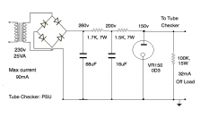
I have got a Tube Checker up and running. Circuit attached for Checker and PSU.
The PSU regulates to 150v off load, and passes 32mA current. However when connected to the Checker it doesn't regulate properly. I get e.g. 180v. So the readings off the 100R resistor in the Checker aren't what you would expect from the curves at 150v. They are, however, around what's expected for 180v.
I built the PSU for small tubes testing hence I only used a 25VA transformer. One other factor is that I set all this up in sunlight, don't know if sunlight affects glow tubes.
Any idea why the glow tube isn't regulating on load? Any other criticisms of the setup?
Attachments
I just stumbled over this thread...
I have some floating around in my lab. I use them as door stoppers. Shoot me a PM if anyone is interested.
Apart from this, using bench supplies is perfectly fine for tube testing. Bench supplies can usually be connected in series, which gives a higher DC voltage.
Also, using a bit of software will turn programmable bench supplies into a curve tracer or a tube/transistor matching system, see here (scroll down to see some examples): GitHub - mbrennwa/PyPSUcurvetrace: Python program for I-V curve tracing of electronic parts using programmable power supplies
look on the auction site for an electrophoresis(?) power supply for high voltage. I found one 500 max at 100ma for $65.00
I have some floating around in my lab. I use them as door stoppers. Shoot me a PM if anyone is interested.
Apart from this, using bench supplies is perfectly fine for tube testing. Bench supplies can usually be connected in series, which gives a higher DC voltage.
Also, using a bit of software will turn programmable bench supplies into a curve tracer or a tube/transistor matching system, see here (scroll down to see some examples): GitHub - mbrennwa/PyPSUcurvetrace: Python program for I-V curve tracing of electronic parts using programmable power supplies
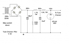
Update - I think this now works. I changed the PSU a bit - put the 100K bleeder resistor before the glow tube. I also used a different glow tube. The readings I'm getting now look correct. I've tried a couple of EL33 and they look right, using the data off the curves.
I'm cautiously optimistic that I now have a working tube checker.....
I'm cautiously optimistic that I now have a working tube checker.....
Attachments
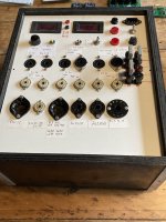
Early days, but I've now tested about 25 of PL33 in triode using the given triode curves at 150v and -5v bias, and the results are as expected. So I can declare this a working emissions tester. Photo attached in its raw state. I'll build a bigger box with more tube bases on it and some kind of switching ability for the pins, but for now I can go on testing tubes with typical bases like the usual octal output tubes. I'll add tube bases as I need them. I'm happy with this.
Attachments

Lovely, Andy.
(insert smiley face) … now all you need is to control the whole thing with a Raspberry PI kit, selecting the DUT (device under test) with a few USB downloaded parameters; the PI could time-delay the heater from the B+, and with very little overhead, could also ramp B+ up 10 volts at a time and record IA measurements. Your controlling laptop would then compose a nice graph of curves. A la the standard charts. In maybe a minute.
/end smiley
Seriously… a worthy project and outcome. The only real difficulty is taking all measurements inside the PI's A-D-C pins, and leveraging its DAC pins to drive the B+, BIAS and FIL supplies.
The very old programmer in me loves this kind of automation: it really is what computers were originally 'made for', along with computing the millionth digit of PI. (Goat laughs… brays… whatever!)
⋅-⋅-⋅ Just saying, ⋅-⋅-⋅
⋅-=≡ GoatGuy ✓ ≡=-⋅
Seriously… a worthy project and outcome. The only real difficulty is taking all measurements inside the PI's A-D-C pins, and leveraging its DAC pins to drive the B+, BIAS and FIL supplies.
Yes, that will be tricky, mainly because the PI does not have an ADC or DAC 😀
One could probable make something with some add-on boards containing ADCs and DACs, but you'd still need voltage multipliers, current buffers, and stuff.
I think it's easier to use programmable bench power supplies and control them from the RPi (or whatever computer you like).
i2c
Yes, I agree … my go-to is generally the ridiculously cheap ($1.95) I2C devices to do ADC and DAC functions; Teensy has basic ADC pins of sufficient resolution to give nice results, built-in. $22.95 boards, or way less.
Still your point of a complexity-driven project is heart-felt. I would use a HV MOSFET series pass device for the [ low to 200+ ] B+ supply perhaps; actually thinking on it, a power-wasting but dirt-easy to implement shunt regulator would really do the trick, along with a small 5 volt op-amp. You what, want to drive potentially up to 50 mA?
50 mA × 250 volts is 12,500 mW of power to wick away. Not really that bad for a smallish heat-sink to accomplish.
Moreover, “shunt type” regulators keep all the control voltages quite low. Volts. IC level voltages. A 24-to–27 volt DC supply could likewise easily be voltage controlled to the 5, 6.3, 12.6 (or other) filament range. And the negative bias business … almost could be one with a negative rail 24 V op-amp all by itself; no real short-circuit protection tho. Might as well just use those MOSFETs for the brutal service they typically must endure in the real world.
Again… I am not trying to make light of the complexity of doing this my suggested way. Rather, I could see a nice all-in-one-bag of parts, sockets, rotary switches and an Arduino, Teensy or Raspberry PI URL linkie to get the program that once assembled would let any experimenter test her own valves and output EXCEL friendly CSV data, prepped and ready to turn into cute graphs. Useful graphs.
⋅-⋅-⋅ Just saying, ⋅-⋅-⋅
⋅-=≡ GoatGuy ✓ ≡=-⋅
So you want to generate the negative voltage between the cathode and ground? Thats a smart move, as it allows direct measurement of grid current over the 100K grid resistor using a 10Meg input impedance voltmeter.
The downside is that your supply needs to be able to sink current, what you can do, is shunt the supply with a 200mA CCS (LM317 CCS) for example.
Ive build approx 4 tube testers so far, but most have become to heavy for daily use. Once you start addding functionality and linear supplies capable of testing the biggest of tubes it becomes heavy and complicated.
I once got around this by building a simple tester that has only one user settable control: G1 voltage. And fixed solid state 250V 125mA supply inside (+-0.5%)
If you know IA at a specified VG you can test the most common recieving tubes on this kind of test box with decent accuracy.
Gas test is just a normally closed push button that shorts a 500K resistor, once you push this in, any grid current will cause a increase in measured anode voltage. If this increase is over 5% there is gas in a tube.
Case and point i reject EL34 tubes if IA increases by more than 5% once you push the gas test.
The uTracer is not a tester, and does not heat up the tube nearly enough to catch runaway tubes, or internal faults that only show up once the tube is at rated plate dissipation.
Yet to build it (have not had the urge yet, a temporary shelved project). I've collected all the parts: a laptop power supply, a bunch of dc-dc converters from ePray with adjustable output voltages, a couple of 12Vdc-12Vdc converters that can have 300 VDC between in and output levels, a bunch of digital meters, several Chinese Bourns(? fakes) mutiturn pots with the mutiturn counters for adjusting voltages, a left over Hammond chassis, ferrite beads and a few dozen sockets. Total cost less than US 100.- and does not weigh a lot.
Static measurements of gm can be made but also a Picoscope can inject AC and then across a small 100 Ohm resistor the oscilloscope can measure the output.
I looked at a curve tracer kit from France and one from The Netherlands but both use pulsed voltages that do not load the plate to its rated dissipation making imho the measurements next to useless.
If tubes are to be matched then they need to be run for 50 hours before matching. Only current matching is not good enough for class AB2 / B which is what most resellers do. (And neither is the pulsed curve tracing at reduced plate dissipation good enough.)
AM
Yet to build it ... Total cost less than US 100.- ... also a Picoscope can inject AC and then across a small 100 Ohm resistor the oscilloscope can measure the output.
$100 parts*, $170 picoscope, plus computer. Why not use programmable power supplies to start with? It's less fuss and can be used in much more flexible ways, if you ask me.
(*famous last words -- the real costs always come out higher than my calculated costs 😉 )
Neither Picoscope not laptop are required, it can be worked stand-alone and from a car battery. (It was intended to take to ham fests).
And in today's environment both oscilloscope / wave generator and computer are already present so do not need to be included in the costs. Forgot to add: the cost of electricity to solder it together and run the test, the cost of solder and the cost of some hook-up wire. 😉
It's a hobby and it's making something that is not commercially available. E.G.: Can you use any commercial available tube tester to run in your tubes at design ratings for 50 hours? The pulsed uTracer's won't do it, neither will the bulk of old tube testers do it.
Can you use any commercial available tube tester to run in your tubes at design ratings for 50 hours? The pulsed uTracer's won't do it, neither will the bulk of old tube testers do it.
The eTracer has a pre-heat option. Maybe it also idles at a preset bias point between readings (I don't remember exactly, as I have not used mine since I moved to using programmable bench PSUs for testing and curve tracing).
- Home
- Amplifiers
- Tubes / Valves
- Simple tube tester using bench supplies?