Thank you Shaan,Yes 1K+220 is perfectly OKAY(I am doing this too). In fact, you may need to modify these values after checking the initial bias, which may not be optimum at first.
Board looking good with parts.
Ok, i'll go with series resistor.
Anoter question do i need little heatsink on BD139/140?
Do i need little heatsink on BD139/140?
Yes. 1"x1" heatsink will do. I used "U" shaped small heatsinks which aren't too good, a little more hotter than I like. But I did this so that the VAS bias would stabilize quickly.
Hi naf. The zeners seem to me to be 1/2 watt rated. You should use a 1watt one.
With 470ohm feed resistor, the dissipation is over 400mW; although less than 500mW, having a larger dissipation margin is good for long term reliability as 1W zeners have thicker wires that can help transfer much of the heat to the copper quickly.
With 470ohm feed resistor, the dissipation is over 400mW; although less than 500mW, having a larger dissipation margin is good for long term reliability as 1W zeners have thicker wires that can help transfer much of the heat to the copper quickly.
Shaan. thanks for your information, i'll paralell the zener and add little heatsink to VAS tr.
I'll paralell the zener.
NO NO NO! DON'T!


Read this to know why you should not:- Can you parallel zener diodes?
dear Esperado,?? 😕
as i'm new to this electronic world.
i think by paralelling the zener it will increase watt rated, just like paralelling elco to increased capacitance.
edit:
Shaan gave me link about paralelling the zener, now i know why.
Last edited:
thank you Shaan, now it's clear to me.
i learn something new.
Last edited:
thank you Shaan, now it's clear to me.
i learn something new.
Happy to help. 🙂
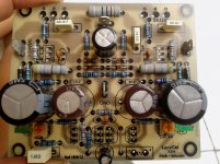
If you cannot parallel Zeners, never, no way, you can use two in serial, making sure their total breakdown voltage is the same that the original single one.Shaan, here my progress on building..
sorry don't have chance to source 1W zener :-(
Or increase the value of the feeding resistance to lower the current.
dear Esperado, thank you very much for your explanationIf you cannot parallel Zeners, never, no way, you can use two in serial, making sure their total breakdown voltage is the same that the original single one.
Or increase the value of the feeding resistance to lower the current.
ie: for 15v, i could use 7v and 8v in serial, right?
regards
naf
dear Esperado, thank you very much for your explanation
ie: for 15v, i could use 7v and 8v in serial, right?
regards
naf
Hi naf
You don't need 1 W zener since there's cca. 10 mA zener current, multiply 15 V, so you end at 150 mW power dissipation on one zener diode. 500 mW zeners are OK.
If you dont have 1,2 k resistor than parallel (one resistor on top other on bottom side) two 2,4 k or 5,6k parallel to 1,5 k etc. It will be easier later to adjust correct value in this way, idea is to parellel them rather than serial connection. 😉
Hi Jay,
I promised to report of the effects of using a 100R resistor between case earth and amplifier star earth. I recently changed my amps over to this arrangement and I am very happy with it. When I measure at the amps o/p on the scope now noise appears to be a little lower. I am not totally sure if that is a real improvement or whether this arrangement just makes it easier to measure noise properly.
Subjectively perhaps it brought a little more refinement but to be absolutely sure I would have to do more tests which I don't feel inclined to do.
Logically this is a very neat completion of my choke regulated scheme and clears up a lingering concern I've had for a while about creating beautifully clean voltage & earth rails and then connecting the amp star ground to what could be a horribly polluted domestic earth and also prevents the amps metal casing acting as some kind of RF aerial that is being injected in the amp.
Now there is strong filtration between the domestic earth, amp casing etc and the amps power supply system. Not sure if further cleaning up of the domestic earth would bring further improvements but for now I happy with things how they are.
Hope this useful
mike
Woaa!!! thank you very very much LC for explanation and hint on building this babyHi naf
You don't need 1 W zener since there's cca. 10 mA zener current, multiply 15 V, so you end at 150 mW power dissipation on one zener diode. 500 mW zeners are OK.
If you dont have 1,2 k resistor than parallel (one resistor on top other on bottom side) two 2,4 k or 5,6k parallel to 1,5 k etc. It will be easier later to adjust correct value in this way, idea is to parellel them rather than serial connection. 😉
not many people/designer willing to explain much detail like this
 You're the man😎
Last edited:
I recently changed my amps over to this arrangement and I am very happy with it. When I measure at the amps o/p on the scope now noise appears to be a little lower.
Hi Mike
If scope measurement showed improvement at noise floor, than this is real improvement not just subjective. The whole idea to control ground currents or at least to know where their paths are in GND, GND star connection, that sounds like an improvement to me. Earth potential connection to the metal case is a must but to sensitive audio signals this brings also the whole spectra of mains noise currents to GND which is bad but almost unavoidable. In this way you gain control over the noise interference currents, directing them to flow away from sensitive GND areas.
Thanks Andrej,
I think you are right but I also know that poor earthing can create havoc with measurement systems so I was not sure which was which in this case 🙂
I think you are right but I also know that poor earthing can create havoc with measurement systems so I was not sure which was which in this case 🙂
Hi naf
You don't need 1 W zener since there's cca. 10 mA zener current, multiply 15 V, so you end at 150 mW power dissipation on one zener diode. 500 mW zeners are OK.
With 1K2 resistor the current at 15v will be over 12mA into the feedback bridge. In my experience the zener current should be higher than this for effctive regulation, requiring 470ohm or so for the zener feed resistor and essentially a 1w zener(from my last year's messed up SSA attempt).
IMHO, the 1/2 watt zener can not regulate the voltage for the total required current, which can be as high as 15mA if the VAS devices have lower gain than usual.
There's 10 V voltage drop on 470 ohm resistor, meaning 21,3 mA current flow, minus 12 mA of current through 1,2 k resistor, what remains is 9,3 mA zener bias current. Zener current regulation required is 9,3 mA +/- 5 mA at max.
To my opinion 500 mW zener can do that without problem, at least what datasheet says. 🙂
- Status
- Not open for further replies.
- Home
- Amplifiers
- Solid State
- Simple Symetrical Amplifier