I had a dodgy connection on an amp last Friday that left me worried. My speaker was okay but could have seen a 30vdc offset, it was a Q Acoustics 3030i and not one of my Celestions luckily. So I looked at a lot of speaker protection circuits, read a few articles on here and Elliott Sounds and then decided I would give it a go myself.
I am crap at electronics but came up with a protection idea. First I messed about with one that works with a PIC controller, I had a simplified circuit from Elliott Sounds to work from but could not work it out. I changed a few components and come up with this, it is just the DC detection part at the moment. The circuit will produce a voltage that is proportional to the DC detected.
I also learnt how to use the basic functions of LTspice. Here a 4vdc offset is detected and 16mV is between the optocoupler and R6. It is 79mV with a 10vdc offset.
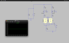
Here is 1.24v between the optocoupler and R6 with a -75vdc offset. Positive dc offsets will produce a result within a few mV of the negative offset.
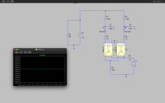
This is the result for a 20hz 75vac sine wave. I had to play with the resistor values, if R1 and R2 are too low the result would be a lot higher than the DC offset I am trying to detect.
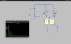
As I stated earlier, I am not great at electronics. I do not know what diodes I should be using. I am assuming the PC817 optocouplers will be ok in this circuit as they are not fully closing. At 75vdc the MCUs ADC will not see more the 1.3vdc so should be safe, I think it can take 3.3v. The ADC has a 100mOhm input impedance, I don't know how to represent this in LTspice and all my results could be wrong LOL. It would be great if someone could help me improve this circuit.
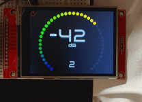
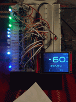
I plan to use a Teensy4.1 MCU to monitor the DC offset, it is what I normally use for my projects. The MCU has an ADC that can receive 0 to 3.3v and can have a 12bit resolution so would be perfect (except they are £30). If a high offset is detected it would ground the speaker outputs, also ground them for anti thump when turning the amp on/off. The teensy needs a 5vdc psu but itself operates at 3.3v. The Teensy is a very powerful MCU, controlling a relay attenuator, touchscreen and remote control it would cycle through the program between 2 and 4 million times a second. Below are pictures of aTeensy, it is simulating controlling a relay attenuator, input relays, power relays and speaker grounding relays with LEDs (I am also terrible at taking pictures of small displays, make it 2.4" and it looks better).
I am crap at electronics but came up with a protection idea. First I messed about with one that works with a PIC controller, I had a simplified circuit from Elliott Sounds to work from but could not work it out. I changed a few components and come up with this, it is just the DC detection part at the moment. The circuit will produce a voltage that is proportional to the DC detected.
I also learnt how to use the basic functions of LTspice. Here a 4vdc offset is detected and 16mV is between the optocoupler and R6. It is 79mV with a 10vdc offset.

Here is 1.24v between the optocoupler and R6 with a -75vdc offset. Positive dc offsets will produce a result within a few mV of the negative offset.

This is the result for a 20hz 75vac sine wave. I had to play with the resistor values, if R1 and R2 are too low the result would be a lot higher than the DC offset I am trying to detect.

As I stated earlier, I am not great at electronics. I do not know what diodes I should be using. I am assuming the PC817 optocouplers will be ok in this circuit as they are not fully closing. At 75vdc the MCUs ADC will not see more the 1.3vdc so should be safe, I think it can take 3.3v. The ADC has a 100mOhm input impedance, I don't know how to represent this in LTspice and all my results could be wrong LOL. It would be great if someone could help me improve this circuit.
I plan to use a Teensy4.1 MCU to monitor the DC offset, it is what I normally use for my projects. The MCU has an ADC that can receive 0 to 3.3v and can have a 12bit resolution so would be perfect (except they are £30). If a high offset is detected it would ground the speaker outputs, also ground them for anti thump when turning the amp on/off. The teensy needs a 5vdc psu but itself operates at 3.3v. The Teensy is a very powerful MCU, controlling a relay attenuator, touchscreen and remote control it would cycle through the program between 2 and 4 million times a second. Below are pictures of aTeensy, it is simulating controlling a relay attenuator, input relays, power relays and speaker grounding relays with LEDs (I am also terrible at taking pictures of small displays, make it 2.4" and it looks better).


Last edited:
An even simpler version, the MCU just needs to check if the signal from the circuit is High or Low. Below 1.15v the signal is Low, this is at about a 4vdc offset. Above 2.31v the signal is High, this is about a 5.5vdc offset. The MCU will detect an offset of 5.5vdc but might detect it above 4vdc when the signal is between Low and High. A 100v 25hz sine wave will not trigger it.

Last edited: