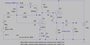
OK, so I hope that life is settling in enough for me to actually try a simple project. So I was thinking of a simple preamp using parts bin bits which includes lots of 12AX7s and 12AU7s. The basic idea is a 12AX7 gain stage direct coupled to a 12AU7 follower with FB from the follower output to the input. Gain is set a bit on the high side intentionally since my power amp is pretty low sensitivity.
Of course my natural tendency is toward mission creep so I thought why not add a simple contour control to the FB loop since that is probably all the EQ I would typically need. R9, R10, C4, and L1 make up the contour control. With no L making a mid/high shelf is no problem but adding the L naturally results in some interactions that cause a big bump around 25k-100kHz at least in the simulation.
Besides the extra very high frequency response my concern is stability. So my first thought was to add a cap (comp cap on the schematic) to roll off response over 30kHz.
So the question is this type of contour control a bad idea over all and if not what would be the best way to stabalize and control HF response?
Attachments
Interesting Schematic.
However, L1 is 4 what? 4H, 4uH, 4mH?
Lots of inductance for L1 will have lots of distributed capacitance (end to end across L1).
I suspect that regardless of the simulation, L1 will self resonate somewhere and give a large wrinkle/ripple in the frequency response.
And, depending on L1, if it has a core that is grounded, there is also the stray/parasitic capacitance of the winding to ground.
I do not see any of this in the schematic, so it is probably not included in the simulation software results.
Then there is the series resonance of L1 and C4. Another item to check. The Q of L1 / C4 should be fairly low due to R9 and R10.
When is negative feedback not negative feedback?
When the total phase is much nearer to 0 degrees than it is to 180 degrees.
I have not used any tone controls for decades.
And the only equalizer I have used was to do some listening (ear training, to get an idea of the sounds of various frequency bands, and how they sounded, versus loudspeaker frequency responses).
By the way, that kind of feedback implementation will reflect different input impedance on the signal source, versus frequency.
A 12AY7 instead of a 12AX7 will give you lower gain, if you do not need the total gain of the 12AX7.
But if by chance, a CD player is your only signal source, the 12AY7 gain would probably be enough for most low input sensitivity power amps. An exception to that would be low amplitude CD recordings, such as many David Chesky CDs (Chesky Records, they are perhaps 10 to 20 dB lower peak recording levels than most CDs.
Happy Preamp Designing, Happy Listening!
Last edited:
I would do this way:
1) With contour enabled no feedback. You could see if you can have the tone control/contour with enough loss so that you don't need FB.
2) With contour disabled you use FB.
1) With contour enabled no feedback. You could see if you can have the tone control/contour with enough loss so that you don't need FB.
2) With contour disabled you use FB.
4H. I need to choose better values to get that inductance down. It turns out the sim is only about 1.2dB peak but as you say in real life it will be more complicated. That is why I am a little bit skeptical of an inductor in the feedback loop. There is probably a better way.
Member
Joined 2009
Paid Member
interesting use of a contour in the fbk!
The gris stopper should be at the grid, i.e. I’d have that grid-cathode diode connect to the other side of the grid resistor.
The gris stopper should be at the grid, i.e. I’d have that grid-cathode diode connect to the other side of the grid resistor.
Member
Joined 2009
Paid Member
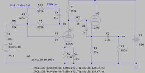
So lest this get out of hand I think that something like this is a better bet. Simple mid and high cut which at full down is -3dB at about 80Hz and max cut of about 9dB. Any further tone control can be added in a separate EQ. later. The follower output should be fine for driving my tube PA and a sub amp if necessary.
KISS.

KISS.
Attachments
Why?I’d have that grid-cathode diode connect to the other side of the grid resistor.
Andy.
Diabolical Artificer,
Bigun said why.
So to put it another way, i say:
"The maximum grid current that can be delivered by R1, 200k, and B+ of 300V is 1.5mA, even under the worst form of clipping of U1, or even if U1 opens up.
The reason for R7, 1k, is to act as a grid stopper for U2.
The diode connected directly to U2's grid, reduces the effectiveness of R7 grid stopper.
If R7 is not there to act as a grid stopper, then take out R7, in that case it is not needed".
Last edited:
The diode connected directly to U2's grid, reduces the effectiveness of R7 grid stopper.
How please? AFAIK a grid stopper is there to reduce the effect of the Miller capacitance. As the diode is biased off due to U2's cathode being at a higher potential than it's grid and by inference higher than U1's anode. What is the diode doing to reduce the effectiveness of R7?
Andy.
"What is the diode doing to reduce the effectiveness of R7?"
With you on that - nothing. It is an anti-spark diode.
With you on that - nothing. It is an anti-spark diode.
> What is the diode doing to reduce the effectiveness of R7?
The diode's anode-lead presents extra metallic area that can pick up (phase-shifted) signal from the anode. The self-oscillation frequency of small triodes can be high, so even a small piece of conductor is not a zero risk.
Place the diode on the other side of the grid stopper resistor, and the Q-spoiling effect of the resistance will be helpful
🙂
I need to learn writing this way!
What is shown originally is the traditional way of connecting the diode. It has no practical differences from the other connection.
I need to learn writing this way!
What is shown originally is the traditional way of connecting the diode. It has no practical differences from the other connection.
Maybe not from the diode's viewpoint, but it is certainly different for suppression of (potential) oscillations.
This seems like a lot of hair-splitting to me. The purpose of the diode D1 is to protect the grid/cathode circuit from a large positive voltage at startup. It can do that job just as well on the other side of the grid stopper resistor.
As Bigun already explained, the grid stopper resistor R7 should be physically located as close the grid pin on the tube socket as possible to do its job of suppressing HF oscillations. Putting the diode between the grid stopper and the grid pin on the tube socket requires that the grid stopper be moved a little farther away from the tube socket. Will this matter much? Probably not. But there is a valid reason to move the diode to the other side of the grid stopper, but no real reason that it should be placed next to the grid pin.
As Bigun already explained, the grid stopper resistor R7 should be physically located as close the grid pin on the tube socket as possible to do its job of suppressing HF oscillations. Putting the diode between the grid stopper and the grid pin on the tube socket requires that the grid stopper be moved a little farther away from the tube socket. Will this matter much? Probably not. But there is a valid reason to move the diode to the other side of the grid stopper, but no real reason that it should be placed next to the grid pin.
Nope!
Whoever sees oscillations here because of 'wrong' diode connection, will have no troubles confirming that it is oscillating without the diode as well.
🙂
Whoever sees oscillations here because of 'wrong' diode connection, will have no troubles confirming that it is oscillating without the diode as well.
🙂
Thanks Rod, makes sense. These minor tweaks can have big consequences especially with twitchy valves like ECC88's & ECC81's who are as stable as Mr Trump.The diode's anode-lead presents extra metallic area that can pick up (phase-shifted) signal from the anode.
I have used these diodes before on cathode followers, beware though when the previous stage is directly coupled, as, if whilst fault finding the valve with diode is left out, it effects the previous stage as the diode is not turned off and will pull the previous stages anode voltage down. That caught me out once, took a while to figure that one out.
Back to the OP's schematic,direct coupling is all well and good but it can be a pain in the **** to set DC conditions correctly, I advise maybe popping in a preset as part of R1 and or R5, at least for a prototype.
Thanks all, Andy.
Last edited:
> Will this matter much? Probably not.
Yes, as I stated - it is a small risk - but not a zero risk.
Yes, as I stated - it is a small risk - but not a zero risk.
- Home
- Amplifiers
- Tubes / Valves
- Simple (sort of) Preamp stability