P { margin-bottom: 0.08in; } I want to add a VU-Meter (older type, analog, not LED) to my 2x20 Watt amp. I'm only interested in pure eye-candy, accuracy of the meter doesn't interest me. With pre-installed rectifier circuit (I hope cheap Ebay models include this) my ideal solution would be...the simplest possable parallel connection to loudspeakers, and I came accross this entry in the forum.....from "djoffe"
http://www.diyaudio.com/forums/solid-state/227309-analog-vu-meter-driver.html
Now I need professional oppinion, if this method works, what values of series resistance would be appropriate? I've read elsewhere that a „Ballistics“ driver is essential...if this is so then I need an absolutely basic op-amp as a buffer. Where would I find a circuit that works on +14.5 Volts? Obliged for any help here, I'm out of my depth.
For gpapag's one-transistor circuit, would you know if, for a supply of 14.5 volts, the transistor could be a BC5478 or if not, any suggestions? And D1...what sort of diode?
Last edited:
For gpapag's one-transistor circuit, would you know if, for a supply of 14.5 volts, the transistor could be a BC5478 or if not, any suggestions? And D1...what sort of diode?
Any cheap small npn should do. A bc547 will be ok.
Since you're not after accuracy, I'd use a cheap schottky diode or even a 1n4148
Any cheap small npn should do. A bc547 will be ok.
Since you're not after accuracy, I'd use a cheap schottky diode or even a 1n4148
Right...great... I'm off to electronic suppliers.
I'll be back.....
the pdf isn't complete. Searching jlmaudio for complete version....
The link works for me...2 page PDF.
Dan.
Fig.1 & Fig. 3 are missing from the pdf. I still haven't found another source
Right...great... I'm off to electronic suppliers.
I'll be back.....
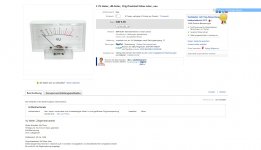
P { margin-bottom: 0.08in; }A:link { } Panic! I've bought two VU- Meters from Ebay (see Thumb)
& I think they may be duds. No response when connected to amp input direct and no response when connectted through this basic one-transistor circuit circuit...
http://www.diyaudio.com/forums/analog-line-level/236845-simple-analog-vu-meter-driver.html
…...entry by gpapag. (However, a very fast connection to speaker and the arrow flies to far side of the scale)!
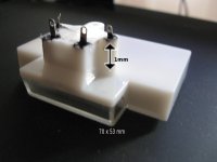
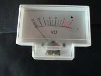
Each picture of a meter that I've seen so far features a long barrel-like enclosure behind...coil and magnet. With these two the extension is quite small (please see pics). Question is, given the dimensions, do these two hold a mechanism or not? If it turns out that the coil-magnet mechanism is just smaller than most and the meters are ok., then I desperately need someone to point me to an alternative basic circuit/driver probably with rectifiers and it needs to work from 14.5 Volts. Please help
Attachments
Last edited:
If it's an a.c. meter movement, all you need is a resistor in series with the meter. The value of the resister will depend on the sensitivity of the meter. Start with something like 3.3k.
How can I verify if it's A.C? It's cheap, I think it's D.C. Im not even sure if it has a solenoid (see previous post)I've been there recently...
Most cheap meters on ebay aren't made for AC but for DC. They need extra rectifiers.
If you have a multimeter, switch it to 'OHMS' to measure resistance.
Connect it to the meter and note whether the meter goes up or down.
Reverse the multimeter leads and look at the meter again. If the VU meter goes up with the multimeter connected either way, it's an a.c. meter movement. If the meter 'pegs' to the left with one of the connections, it's a d.c. meter movement. If it's a d.c. movement, why not just feed the meter through a diode (to change the a.c to d.c.)?
O.k., the meter test indicates that it's D.C. With the signal fed through a diode it indicates nothing. This shouldn't be bloody rocket science, what's wrong?
You ARE feeding the meter from the output of your amplifier aren't you?
You can't feed the meter from a line level source.
If the meter needle moves to the left, reverse the diode.
You can't feed the meter from a line level source.
If the meter needle moves to the left, reverse the diode.
Thanks for your patience, I thought all these meters were line level. I don't want to damage speakers or amp., does the meter just go straight accross a speaker (parallel) or in series please?
The meter goes right across the speaker output. You will need a series resistor to keep the meter from 'pegging' at normal listening levels. The value of the resistor will depend on your listening habits.
- Status
- Not open for further replies.
- Home
- Source & Line
- Analog Line Level
- simple solution for VU-Meter