Hello Fellow Simple SE DIYers,
Like many of you I have a collection of parts in my garage and I need some tunes when I am working at my bench. Just single end tunes is all I need.
Has anyone hooked up one of those ten pound power transformers that George found on e-bay for $15 to a Simple SE amplifier? The power transformer has 6.3 volt taps. Can I use one of those taps plus a resistor to heat up the 5 volt heater of the rectifier? I am sure that it can be done. Has anyone worked out what value of resistor? What pair of leads?
My estimation is 6.3 – 5 = 1.3 volt drop at 2 amps gets 0.66 ohms. E/I = Ohms
DT
All just for fun!
Hello,
Too late to edit.
As Ty_Bower points out in the other thread about the ten pounder there is no center tap to operate the tube rectifier.
DT
Too much fun!
Too late to edit.
As Ty_Bower points out in the other thread about the ten pounder there is no center tap to operate the tube rectifier.
DT
Too much fun!
No centre tap, but you could use a hybrid rectifier, a tube rectifier plus 2 SS diodes, apparently works well.
No centre tap, but you could use a hybrid rectifier, a tube rectifier plus 2 SS diodes, apparently works well.
Hello,
I can almost recall seeing a full bridge rectifier made from a dual diode rectifier valve and two solid state diodes. No current will flow until the valve heater is hot.
Is that the concept?
Thank you.
DT
All just for fun!
Has anyone hooked up one of those ten pound power transformers that George found on e-bay for $15 to a Simple SE amplifier?
Not yet. It looks like it would be easy to do, and yes I would use a resistor. I have the transformer and the resistor, but I don't have a working Simple SE board! I have the crusty old one that has been used for all sorts of experiments including anything that might blow up. If I get time tomorrow I will try to fix it.
Pure conjecture at this point...until I actually try it:
Install the SS diodes BACKWARDS. Run a jumper from the SW1 terminal closest to the front of the board (the diodes common) to one of the ground terminals at T1-RED-YEL. This creates the SS part of the hybrid bridge. Add a resistor in series with one of the 6.3 volt secondaries and connect it to the T1-YEL terminals. This should result in a B+ in the 325 to 360 volt range. This should work with the usual tubes and a 3K ohm OPT, or a set of 6V6's and a 5 or 6K OPT.
Like the man usually says.....do you want the good news first...or the bad news.
Good news:
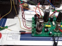
After changing a few parts in a dead SSE board (how did I blow a 12AT7) it is now live. I removed the SS diodes, turned them around, and reinstalled them. I used a 0.8 ohm 7 watt resistor to feed the 5AR4. I wired it up just like described above and flipped the switch. No boom, no smoke.
Bad news:
My estimates for the B+ were higher than I really get. Using a Chinese 5AR4 I get 285 volts of B+ under load. 5AR4 heater is 5.05 volts. Now 285 volts isn't going to rock the world using any tube that will fit in the board. So I just stuffed in some vintage smoked glass RCA 6V6GT's wired them for triode and let both watts rip.
Good news:
After changing a few parts in a dead SSE board (how did I blow a 12AT7) it is now live. I removed the SS diodes, turned them around, and reinstalled them. I used a 0.8 ohm 7 watt resistor to feed the 5AR4. I wired it up just like described above and flipped the switch. No boom, no smoke.
Bad news:
My estimates for the B+ were higher than I really get. Using a Chinese 5AR4 I get 285 volts of B+ under load. 5AR4 heater is 5.05 volts. Now 285 volts isn't going to rock the world using any tube that will fit in the board. So I just stuffed in some vintage smoked glass RCA 6V6GT's wired them for triode and let both watts rip.
Attachments
Hello George,Like the man usually says.....do you want the good news first...or the bad news.
Good news:
After changing a few parts in a dead SSE board (how did I blow a 12AT7) it is now live. I removed the SS diodes, turned them around, and reinstalled them. I used a 0.8 ohm 7 watt resistor to feed the 5AR4. I wired it up just like described above and flipped the switch. No boom, no smoke.
Bad news:
My estimates for the B+ were higher than I really get. Using a Chinese 5AR4 I get 285 volts of B+ under load. 5AR4 heater is 5.05 volts. Now 285 volts isn't going to rock the world using any tube that will fit in the board. So I just stuffed in some vintage smoked glass RCA 6V6GT's wired them for triode and let both watts rip.
The witches and goblins are thick at my door. Happy Halloween to you.
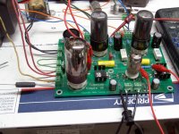
That is a very handsome 0.8R resistor. I hope that you don’t think I was being an Oskar the Grouch.
Are those Electra Print output transformers? I bet they sounds nice. I can see some single end tuned for my garage.
Today I have been trying my hand at using a new router to cut driver (MTM) openings for open baffle speakers.
Thanks for your efforts today!
DT
All just for fun!
The witches and goblins are thick at my door. Happy Halloween to you.
I got a whole bunch of candy left over since it rained most of last night.
I hope that you don’t think I was being an Oskar the Grouch.
It's an experiment that has been on my list for a while. I needed to find out how much voltage these transformers will provide in a real world application (before the price goes up again). I plan to stuff some SS diodes into the 5AR4 socket to see what I get. I need about 350 volts for SSE and SSP boards. It doesn't look like these are going to get there. I measure exactly 235 volts on the secondary unloaded and 234 volts with a 120 ma load.
Are those Electra Print output transformers?
They are older Transcendars. I bought a pair of them on Ebay several years ago. He said that they were leftovers from a customer designed 300B amp. I liked them so much that I bought 20 of them for a good price.
Hello All,
I am considering applying an off board Full Wave Bridge Rectified and connecting the rectified DC at the SW1 terminal. Does anyone see any potential issues?
I am also considering adapting some old school real pentodes to play with triode, pentode and UL versions (version for a day) of this amplifier. I have a couple of NOS JAN 837’s. Any thoughts or fun to add (yes the heaters will need separate 12 volt hookup)?
DT
All just for fun!
- Status
- Not open for further replies.
- Home
- More Vendors...
- Tubelab
- Simple SE meets ten pounds of power transformer