Hello,
I'm slowly working to get my Simple SE assembled. I'm looking for some suggestions for the Cathode resistors for various tubes.
I'm using a Hammond 274 transformer, 5AR4, and a Triad C-14X choke. My output transformers are 5K Edcors.
I'd like to install a rotary switch with a few resistors for various tubes. I looked at George's site and the information provided for the B+, tubes and resistor combos. I'm looking for suggestions...
I'd like to run KT88s, 6L6s, maybe 6V6s for now. I have a dual gang 6 position switch I ordered from Mouser so I can select various resistors.
I did see some posts with switches, but it looks like people were switching a resistor in parallel for one different tube. I thought the rotary would give me a few more options.
Thanks...Dave
This is mine:
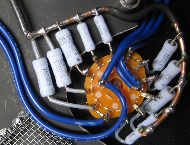
There is a 680 ohm on the board and the following are switched in parallel by the 6-position rotary:
3.3k (for ~560ohms)
1.5k (for ~470ohms)
1.2k (for ~430ohms)
910 (for ~390ohms)
750 (for ~360ohms)
680 (for 340ohms)
I made a spreadsheet to help come up with target values and calculate the necessary power ratings.
...oh and you won't be able to run 6V6 with that amount of B+. It's possible to do it by modifying the power supply filter to switch from CLC to LC, as was brought up recently in another thread.
Russ,
Thanks for sharing and I ejoyed your website. I did not see your spreadsheet posted anywhere on your site. Do you still have your data available.
When you did your test points, did you just set it up so the points measured across the cathode resistor. I plan to do the same.
Dave
Thanks for sharing and I ejoyed your website. I did not see your spreadsheet posted anywhere on your site. Do you still have your data available.
When you did your test points, did you just set it up so the points measured across the cathode resistor. I plan to do the same.
Dave
Yes, the test points are across the resistor so I have to do the math when measuring. I have the original spreadsheet kicking around. I'll post it tonight if I remember.
This is mine:
(photo removed for space)
There is a 680 ohm on the board and the following are switched in parallel by the 6-position rotary:
3.3k (for ~560ohms)
1.5k (for ~470ohms)
1.2k (for ~430ohms)
910 (for ~390ohms)
750 (for ~360ohms)
680 (for 340ohms)
I made a spreadsheet to help come up with target values and calculate the necessary power ratings.
Russ,
The resistors in the photo are 3W rating, unless mine eyes deceive me. Is your 680R on the board in R17/R27 the same? Or is it 5W as a hedge against your switch failing or the resistor you are placing in parallel failing open?
Just wondering, or are you playing a little V^2/R action for each leg to determine a power handling requirement?
Since I am planning a similar scheme (in another recent thread), I am interested in this too.
~Brad
The 680s are the 5W type. The rest are 2 or 3W, depending. See the attached spreadsheet. The columns may warrant some explanation:
B) The expected cathode current from George's table.
C) The total cathode resistance I am shooting for. Tweak these to get the Vk that you like.
D) The actual cathode resistance calculated from "R1" and "R2 avail".
E) The target cathode-to-grid voltage from Ik and Rk.
F) The total power dissipated by the cathode resistor(s)
G) The on-board resistor "R1".
H) The power dissipated by "R1".
I) The exact "R2" value needed in parallel with "R1" to get the target "Rk" value.
J) The power dissipated by the ideal "R2".
K) The actual "R2" value, based on what is available.
L) The power dissipated by the actual "R2" resistor. The resistor should be rated at least twice this amount.
Attachments
Thanks Russ. I had a whole 2 minutes to look at your information today because work was so busy. I see you are giving yourself a few different current settings for each tube with your switch resistor configuration.
I'm in the middle of my build and I need to order a few more items from Mouser. I think I am going to determine safe values for the tubes (KT88, EL34 and 6L6GC) and order these values.
I appreciate you sharing your data. I plan to look more tomorrow. I am also going to provide a set of jacks for current measurement for cathode resistor (like you have).
Dave
Hi,
Firstly, thanks to Metaruss for sharing his ideas.
I'm running my freshly finished Tubelab SSE in triode mode with 6P3S-E tubes right now and I'm also willing to put a Cathode resistor selector to be able to do some tube rolling (I'll soon receive some EH Kt88).
I'm just wondering about how to wire the selector to the amp.
I made a test rig outside the amp witch works, but my wiring do not look like that of Metaruss (witch has a lot more wire coming out from the selector outputs and from pos 1 and 7 of the selector)
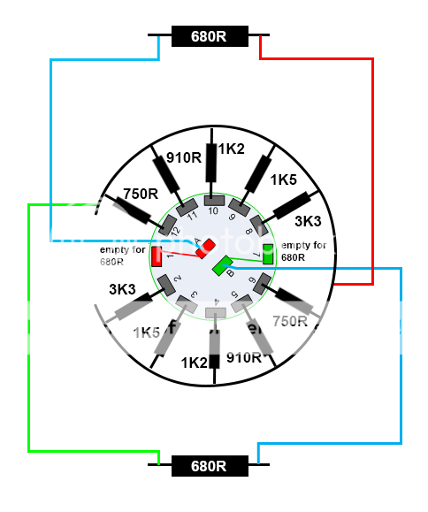
This is how I forecast to wire the selector (this wiring works in test rig outside the amp), Am I doing something wrong? The 680R res are the fixed res soldered on the amp.
I think you do not need to connect the #1 and #7 lugs to the the A and B lugs, when the switch is in this position only the 680 resistor will be in circuit.
For the fixed 680 ohm resistor if you can get a suitable one of 1% tolerance then your actual paralleled resistances will be closer to your target values.
For the fixed 680 ohm resistor if you can get a suitable one of 1% tolerance then your actual paralleled resistances will be closer to your target values.
Thanks a lot spendorite 😉
I will not connect 1 to A and 7 to B.
I've already controlled the values with res in parallel and they are quite fair (even with my current 5% 5W 680R res).
So my wiring is good?
I will not connect 1 to A and 7 to B.
I've already controlled the values with res in parallel and they are quite fair (even with my current 5% 5W 680R res).
So my wiring is good?
Thanks a lot Spendorite, the selector works wonder 😉
Now I have some troubles with humming (low hum) in UL mode (nothing in Triode mode), but I will make another thread to leave this one clean.
Now I have some troubles with humming (low hum) in UL mode (nothing in Triode mode), but I will make another thread to leave this one clean.
Last edited:
Hello everyone,
I made my SSE with a selector switch for 3 different values of resistors copying the Russ idea and I installed 3 jacks (L, G, R) to have measurement points of cathode voltage.
I soldered resistors of 750 ohms on the PCB and left a pair of lugs on the switch, so when it is in this position only the resistor 750 ohms will be in circuit.
The values in the switch are 3K3 and 1K5, then I have this configuration:
KT88 = 750 + 3K3 ~ 500 ohms
6p3s (6L6) = 750 + 1K5 ~ 611 ohms
6ac7 (EL34) = 750 ohms
The switch works very well and the results are satisfactory, but I believe that the tubes are working below the ideal current capacity.
My loudspeakers has good sensitivity (about 95 dB) but I need to put the volume pot above the middle range for good volumes of sound and at this level there is already a bit of distortion.
I'm thinking of reducing the values of cathode resistors, increasing the values on the selector switch. See the voltages that I measured today and give me your opinion:
B+ ~ 450 VDC
Cathode:
KT88 = 500 ohms = 36 VDC (measured) ~ 72 mA of current (calculed)
6L6 = 611 ohms = 38 VDC (measured) ~ 62,2 mA of current (calculed)
6ac7 = 750 ohms = 41 VDC (measured) ~54,7 mA of current (calculed)
Am I on the right way?
Thanks,
Antonio
With your 95db efficient speakers you you should have loud volume levels long before your volume pot
reaches the 12 o'clock position, especially if you have it in UL mode.
Was it fine before you installed the switch ?
The measurements you posted are fine, lowering the resistor values will not get you much more power output.
Maybe the problem lies with your vol. pot or the input resistors.
reaches the 12 o'clock position, especially if you have it in UL mode.
Was it fine before you installed the switch ?
The measurements you posted are fine, lowering the resistor values will not get you much more power output.
Maybe the problem lies with your vol. pot or the input resistors.
Hi spendorite,
I started the SSE with the switches, so I have no parameters to answer. I did a few test without the switchs because I was sure that would install them.
My volume pot is an Alps Blue Velvet 50K. It seems to me that is a good potentiometer.
What are the the input resistors? Sorry for the question, but I'm completely newbie on the subject.
Thanks,
Antonio
I remembered today,
The basic rule is "lower value of resistors = more cathode current = more power dissipation by tubes", right?
I still think this is one of the ways.
Thanks,
Antonio
The measurements you posted are fine, lowering the resistor values will not get you much more power output.
The basic rule is "lower value of resistors = more cathode current = more power dissipation by tubes", right?
I still think this is one of the ways.
Thanks,
Antonio
Is your volume pot a log type or linear type, it should be a log type (audio taper).
If you want to run the tubes hotter by lowering the cathode resistors to get more
power you you can try that, I doubt you will hear much of a difference, your
tubes will have a shorter life.
The input resistors are R11, R12 right channel and R21, R22 left channel.
If you want to run the tubes hotter by lowering the cathode resistors to get more
power you you can try that, I doubt you will hear much of a difference, your
tubes will have a shorter life.
The input resistors are R11, R12 right channel and R21, R22 left channel.
The volume pot is a log type.
The input resistors are:
R11, R21 = 221K OHM 1/4W 1% Metal Film AXIAL, YAGEO
R12, R22 = 100 OHM 1/4W 1% Metal Film AXIAL, YAGEO
Is the problem with resistors related with the parameters or their quality?
The components of the PCB were purchased from Digikey, as indicated by Tubelab.
I was looking at the computer simulations in the Tubelab site and really there is not much difference of the power out betwen a resistor of 330 and another 560 Ohm for a KT88.
I am aware about the problems with life tubes in this case. Thanks for the help, I'll think better of it.
Antonio
- Status
- Not open for further replies.
- Home
- More Vendors...
- Tubelab
- Simple SE Cathode Resistor Values