I realised that I have never hear the sound of a single ended tube amplifier, never tried to build one, therefore decided to put together a proof of concept, very simple and on the cheap.
Goals:
1) Use tubes that I have, nothing fancy. I got some 6P41S and 6N1P tubes.
2) Output power 10W (AVG), no gNF, only local feedback, less than 3% THD.
3) Cheap output transformer from China, 3K3:8ohms, 15W (claimed)
4) Use cheap SMPS for power supply.
The schematic is very simple, just 1/2 6N1P input stage and two 6P41S in parallel, self-bias, class A only, no g1 current.
I was a bit surprised that it actually works quite well, I get around 10W before clipping starts due to g1 current, but this is enough to drive my Monitor Audio Bronze BX5 speakers. Also, there is zero hum on the speakers with the volume tap at max.
The bass is not as strong as in my push-pull amp, probably could do with a better OPT, but Pavarotti, Il Volo, Aretha Franklin all sound great.
Here are some pictures, improvement suggestions are very welcome. I'm planning to add a Mosfet to allow A2 to see how much power can I get without too much distortion. I will also do some more precise distortion and bandwidth measurements, I'm interested to se how good (or bad) the OPT is.
Then you must change to fixed bias and DC-coupling between mosfet and output tubes.I'm planning to add a Mosfet to allow A2 to see how much power can I get without too much distortion.
Plate voltage will also become essentially (55...60 V) higher.
Thank you! I've to add a negative supply for both the mosfet source and the fixed bias.Then you must change to fixed bias and DC-coupling between mosfet and output tubes.
Plate voltage will also become essentially (55...60 V) higher.
Edit: I can lower B+ to around 390, will bias accordingly. The 6P41S datasheet says at least 14W for plate dissipation, right now they are around 18.5W quiescent. Based on reports around here they should be safe at up to 20W.
Last edited:

I've been playing with LTSpice too. Looks like distortion goes up quite quickly when entering A2. I will also try the same with GU-29, and GU-50, got some of them. I don't believe for a second I'm getting 15W 1.6% THD with real HW though 🙂I made some quick simulations. It seems that triode connected 6P41S has so low mu that much extra power can not be squeezed, maybe one...two watts or so (from one tube).
Here are some distortion measurements. As expected, LTSpice is a bit optimistic, but I like the fact that harmonics decrease in order. Using REW + Focusrite Scarlett Solo, input connected to the 8ohm load via a passive 1/10 divider.
1W (2.82V RMS)

5W (6.32V RMS)

10W (9V RMS)

The Chinese output transformer handless low frequencies quite well:
Freq Vout (RMS, 8ohm load)
30Hz 8.66V
40Hz 8.75V
100Hz 8.92V
1Khz 9.02V
1W (2.82V RMS)
5W (6.32V RMS)
10W (9V RMS)
The Chinese output transformer handless low frequencies quite well:
Freq Vout (RMS, 8ohm load)
30Hz 8.66V
40Hz 8.75V
100Hz 8.92V
1Khz 9.02V
What are you measuring the distortion of here? This is typical of what I'm getting at 1W out of 4 PSE 300B amps I'm repairing at the moment.

Parallel SE prototype amp, 2x6P41S, as described in post #1, measurement setup described in post #6 above.What are you measuring the distortion of here? This is typical of what I'm getting at 1W out of 4 PSE 300B amps I'm repairing at the moment.
View attachment 1047899
PS. The hardware you are testing is miles ahead of this one, both in quality and especially cost.
Last edited:
Not noise performance though by the look of it!PS. The hardware you are testing is miles ahead of this one, both in quality and especially cost.
Well, all my supplies are SMPS based, DC output, I do not get a lot of 50/100Hz noise, yes. Your amp has a lot of iron, DHT tubes which are prone to hum. Is easier in my case.Not noise performance though by the look of it!
Update.
Had some more time to play with the amplifier. First, I replaced the 6N1P with an EC86 (PC86 actually), which is a very linear triode. The result was not good, it looks like there is some distortion cancellation going on between the 6N1P and the 6P41S, because, while the driver output waveform is almost perfect with the EC86, the resulting output signal distortion is higher.

Then I went back to the 6N1P, and started playing with the working point. Found that moving the point to lower plate voltage and a slightly higher current makes a big difference, the distortion at 10W is now half of what it was originally (1.12% vs 2.22% @1Khz, no gNF):


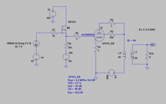
Updated schematic, with measured voltages and R3 changed from 1.1K to 750 ohms.

I believe this is not too bad for such a simple circuit with cheap components.
Had some more time to play with the amplifier. First, I replaced the 6N1P with an EC86 (PC86 actually), which is a very linear triode. The result was not good, it looks like there is some distortion cancellation going on between the 6N1P and the 6P41S, because, while the driver output waveform is almost perfect with the EC86, the resulting output signal distortion is higher.
Then I went back to the 6N1P, and started playing with the working point. Found that moving the point to lower plate voltage and a slightly higher current makes a big difference, the distortion at 10W is now half of what it was originally (1.12% vs 2.22% @1Khz, no gNF):
Updated schematic, with measured voltages and R3 changed from 1.1K to 750 ohms.
I believe this is not too bad for such a simple circuit with cheap components.
- Home
- Amplifiers
- Tubes / Valves
- Simple SE Amplifier