a single winding full wave doubler ensured balanced voltages, unless of course the actual capacitance is off even if the labels says so....electrolytic caps are not known for tight tolerances like in film cap's hence the use of equalising resistors serving as bleeder too...
i have an issue with this, if the ct is not exactly located as in bifilar winding, then the imbalance can be a problem too..
I'm curious, how much imbalance have you seen in practice? Or perhaps, how inaccurate have you seen for a CT? I can imagine a turn either way but that pales into insignificance against the tolerances of 'lytics.
The circuit reminds me of a balanced input...sort of... Could it be that the (especially HF) rubbish, decoupled by C14 and C15, would be better handled if drained to the centre tap, "away" from the amplifier common...?
My suspicion is further emphasised towards the above, by the fact that the negative on a diode bridge is used as a common (thick black line)..?
The complete circuit diagram, more than ever, would've helped further...
My suspicion is further emphasised towards the above, by the fact that the negative on a diode bridge is used as a common (thick black line)..?
The complete circuit diagram, more than ever, would've helped further...

i want to get Murphy out as much as i can, hence my post....I'm curious, how much imbalance have you seen in practice? Or perhaps, how inaccurate have you seen for a CT? I can imagine a turn either way but that pales into insignificance against the tolerances of 'lytics.
Voltage balance is good with mains transformers due to the very high permeability of silicon steel laminations, so that only the turns count matters (commercial CT transformers will have exactly matching turns counts). Resistance imbalance is often poor though, but not a big issue here.i have an issue with this, if the ct is not exactly located as in bifilar winding, then the imbalance can be a problem too..
diy'ers need to take care, while the center tap is not really required, make sure the voltages are equal on either legs...
Neither voltage or load imbalance are that big of a deal with the center tap in place. In fact you can draw totally independent currents on the B+/2 and B+ taps. Those of us who play with cheap tubes and need a lower g2 voltage do this all the time. Big solid state power amps do it too - with multiple voltage taps for class G or H. Voltage division won’t remain totally equal under load, but it’s not a problem because neither half can go above it’s unloaded voltage. Well, maybe a transient if you’re using choke input filters instead of just caps.
If the voltage is a bit unbalanced to begin with (if the tap is slightly off center), you will get some 50/60 Hz ripple in addition to 100/120. Every other charging pulse is a bit bigger. Not ideal, but it won’t blow up either.
If the voltage is a bit unbalanced to begin with (if the tap is slightly off center), you will get some 50/60 Hz ripple in addition to 100/120. Every other charging pulse is a bit bigger. Not ideal, but it won’t blow up either.
if that amp were mine, that center tap would have been long gone by now....
a single secondary winding, two diodes and two caps would have been the simplest way to implement this psu, but then the designer was constrained to use available transformer in the market where probably they got a very good deal since they were making these preamps in volumes...
DIY'ers simply do not have that luxury...
Last edited:
I don't think anyone has mentioned this and perhaps I am wrong, but doesn't the centre tap allow the full value of the capacitors to be effective? Without the centre tap the two capacitors are in series and therefore their value is reduced. And of course lower voltage capacitors may be used when in series or with the centre tap.
They are still effectively in series, center tap or no center tap. It doesn’t magically give more energy storage.
I wasn't expecting magic, just my slow brain trying to grasp the situation. Yes, I can see that even though the centre tap is between the capacitors, the two capacitors are still between V+ and ground, so still in series.
the caps are in series, center tap or no center tap.....I don't think anyone has mentioned this and perhaps I am wrong, but doesn't the centre tap allow the full value of the capacitors to be effective? Without the centre tap the two capacitors are in series and therefore their value is reduced. And of course lower voltage capacitors may be used when in series or with the centre tap.
think about it, energy stores in Joules = 1/2CV^2
without the center tap, total C is half but voltage is full voltage,
with the center tap, C is C but V is half, so what is the difference?
The centre tap keeps the transformer secondary windings at ac ground, too.
indeed....They are still effectively in series, center tap or no center tap. It doesn’t magically give more energy storage.
"The centre tap keeps the transformer secondary windings at ac ground, too."
all should know by now that all power supply filter caps are effectively ac grounds or zeros, all of them....
a single secondary winding, two diodes and two caps would have been the simplest way to implement this psu, but then the designer was constrained to use available transformer in the market where probably they got a very good deal since they were making these preamps in volumes...
ARC has their transformers custom made.
https://schottcorp.com/
Hello everyone.
Thanks for all the support. 😀
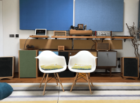
I ended up going for a pair of 45uF Shizuki caps across the centre tap followed by a single 45uF across the full B+
The purpose of doing this was to remove the transformer from the preamplifier case to be able to reduce the EMF from stray fields. The transformer was replaced and I had been fighting with hum and had shielded all that was possible and there was still some left.
Those Shizuki caps do sound very good compared to the originally specified Sprague atoms, and the low level hum is gone now, so very happy.
The external Power supply is not exactly in the aesthetic of the ARC unit, as I had an old wooden box and repurposed it, but it does blend in to the rest of the system.


Great!
Thanks for all the support. 😀
I ended up going for a pair of 45uF Shizuki caps across the centre tap followed by a single 45uF across the full B+
The purpose of doing this was to remove the transformer from the preamplifier case to be able to reduce the EMF from stray fields. The transformer was replaced and I had been fighting with hum and had shielded all that was possible and there was still some left.
Those Shizuki caps do sound very good compared to the originally specified Sprague atoms, and the low level hum is gone now, so very happy.
The external Power supply is not exactly in the aesthetic of the ARC unit, as I had an old wooden box and repurposed it, but it does blend in to the rest of the system.
Great!
Attachments
- Home
- Amplifiers
- Power Supplies
- Simple question to help me understand why?