I am working on a project with 12 rectifier diodes. I was originally planning to use the Aavid 513201B02500G heatsinks recommended in the BoM for the Universal Power Supply Board. They have a normal thermal resistance of 8 C/W. However, they will take a lot of space. I'm now thinking of using a slightly larger heatsink with a thermal resistance of 3.7 C/W and placing one diode on either side of the heatsink. Overall the space consumption should be considerably less.
Are there any pitfalls I need to be aware of doing this?
Are there any pitfalls I need to be aware of doing this?
Most power supply rectifier diodes do not need heat sinks and are constructed that way They only drop a 1/2 volt so there power cunsumption is low. Do you know the current they will pass? Divide by 2 and multiply by duty cycle for the power they will dissipate. Then check the diode data sheet for power handling.
I looked at the schematic in your link. It looks like each leg has four diodes in parallel, two schottky's and two normals. I can't see that as being correct, is that really how it's designed, or does one choose which element to put in?I am working on a project with 12 rectifier diodes. I was originally planning to use the Aavid 513201B02500G heatsinks recommended in the BoM for the Universal Power Supply Board. They have a normal thermal resistance of 8 C/W. However, they will take a lot of space. I'm now thinking of using a slightly larger heatsink with a thermal resistance of 3.7 C/W and placing one diode on either side of the heatsink. Overall the space consumption should be considerably less.
Are there any pitfalls I need to be aware of doing this?
As for heatsinking, all diodes require a path to eliminate heat.
Axial diodes are generally spec'd so that a pcboard with specific lead lengths and pad sizes will meet the heatsink requirement. Axial diodes by design, rely on the leads to carry away junction dissipation, sinking the body is not very effective, nor is blowing air on them. However, if the demands are small, both techniques may be sufficient.
TO- style devices do indeed require heatsinking if they are to carry their full rated current.
Some larger devices are rated based on DC current, some on half sine excitation with overall full current spec'd. For example, a 25 ampere bridge will carry 25 amperes when properly sinked, but not all four diodes passing 25 amps, but 25 amps half sine each.
If you choose to use to use a TO- device without sinks, then you'll have to consider the derating of the device.
In all cases, the intent is to not exceed 150 C at the junction (regular silicon).
jn
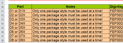
The Bill Of Materials includes the magical word "or".It looks like each leg has four diodes in parallel, two schottky's and two normals. I can't see that as being correct, is that really how it's designed, or does one choose which element to put in?
The PCB Layout only has room for one or the other but not both.
Attachments

The Bill Of Materials includes the magical word "or".
The PCB Layout only has room for one or the other but not both.
As I suspected, thanks.
The question I still have is, it still appears to parallel two like devices. Diodes will tend to runaway thermally in parallel, one device will end up carrying all the current.
When two dice are put into a common package, there is no guarantee that they will share equally either, even if they are adjacent dice from the wafer.
jn
If you are concerned that this design might be dangerous, it might be a very good idea to contact the folks who are selling the boards in the diyAudio online store, and convey your doubts & worries. Hundreds of people have already bought and built these boards; if you firmly believe they are "living on borrowed time," why not let everyone know very quickly. There's a link to the sales page, in post#1 of this thread.
The BoM for the Universal Power Supply Board is for dual diodes (depicted as two parallel in the schematic). I won't be using dual diodes and my project is not that power supply. I made the reference merely to highlight the heatsink type and the source of my original guidance on which sink might be useful.
I take on board I should check the thermal dissipation of the TO-220 devices I was planning to deploy as they will be used for modest current (e.g. 5A continuous) versus their spec. My presumption was, however, that this would conclude the need for a heatsink or at least that use of one would be sensible precaution.
So, back to my question. Assuming a heatsink is necessary/advisable are there issues attached to slapping a diode on either side of the sink (if thermal resistance of the larger heat sink is less than half that of the one used for one diode)?
(The more I think about this the more I think that I need an enclosure with a sidewall heat sink because of shear space limitations but it would good to understand the response to the above.)
Last edited:
If you are concerned that this design might be dangerous, it might be a very good idea to contact the folks who are selling the boards in the diyAudio online store, and convey your doubts & worries. Hundreds of people have already bought and built these boards; if you firmly believe they are "living on borrowed time," why not let everyone know very quickly. There's a link to the sales page, in post#1 of this thread.
Given the fact that hundreds have already used it, and the fact that diodes aren't dropping like flies, I would tend to believe that there is sufficient headroom in the design to survive only one diode working per leg.
If people begin to have problems, then looking further is justified.
No need to believe the sky is falling however.
But good design practice is certainly justified if one wishes to push the diodes to their design limits.
jn
So, I back to my question. Assuming a heatsink is necessary/advisable are there issues attached to slapping a diode on either side of the sink (if thermal resistance of the larger heat sink is less than half that of the one used for one diode)?
Thermally, no. Your math is good.
A common heatsink would require isolation pads if the backside of the diodes are connected to the chip backside. If you buy isopak style with integral plastic isolation, no problem.
jn
The Forum do not take kindly to constructive criticism.If you are concerned that this design might be dangerous, it might be a very good idea to contact the folks who are selling the boards in the diyAudio online store, and convey your doubts & worries. Hundreds of people have already bought and built these boards; if you firmly believe they are "living on borrowed time," why not let everyone know very quickly. There's a link to the sales page, in post#1 of this thread.
Assuming a heatsink is necessary/advisable are there issues attached to slapping a diode on either side of the sink (if thermal resistance of the larger heat sink is less than half that of the one used for one diode)?
A heatsink thermal resistance value is typically for free air location, with the heatsink in the appropriate orientation (eg. vertical for free air for that sink) and with a nominal device attached at the designated location (eg. TO220).
If you add another device to the rear, in the same relative position, then I'd be suggesting the thermal resistance of the sink would remain effectively the same, as the transfer region for the heat entering the sink is effectively the same, and the new part would likely not alter the free air flow or radiating surface area.
But of course if you run each device at the same dissipation power level, then their junction temps will be effectively twice as high. So you need to operate the devices at half their original power dissipation to keep similar junction temp.
Given you are wanting to use a new sink with about half the Rth, then doubling the input power in to that sink will give approx. same case temp for the devices. So your aim is fine, as long as free air conditions are ok for that one sink, compared to using 2 sinks - that is equipment layout dependant.
Last edited:
- Status
- Not open for further replies.
- Home
- Amplifiers
- Power Supplies
- Simple question regarding heatsinks for diodes