
You may find more relevant feedback doing some research on the "compact amp", which was a 6V6 amp design that's quite similar to this one.
Here is the 1961 article...
Compact 6 Watt Amplifier
Here are more random DIYer variations
The Ultra Compact Club
The Bruce Heron amps have been on my "want to build" list for a while too.
You'll find most all of the Bruce Heron projects here
DIY AUDIO PROJECTS - Do-It-Yourself Hi-Fi for Audiophiles
Compact 6 Watt Amplifier
Here are more random DIYer variations
The Ultra Compact Club
The Bruce Heron amps have been on my "want to build" list for a while too.
You'll find most all of the Bruce Heron projects here
DIY AUDIO PROJECTS - Do-It-Yourself Hi-Fi for Audiophiles
I have enjoyed listening to my Class A self inverting push pull amplifiers.
I have used NPN current sinks for the output tube paralleled cathodes.
I also used a DC choke as a current sink for the output tube paralleled cathodes (there was a resistor in series with the choke to set the self bias quiescent current to the designed amount).
The self inverting push pull amplifiers are really simple to design and to build.
If you do not need the power, a good design can please the listener.
"You should make things as simple as possible, but no simpler" - Albert Einstein
But now I will convert most, or all, of my self inverting amplifiers to Class AB push pull amplifiers.
Have anyone tried this circuit, I really like the simplicity of the schematics.
I am wondering if someone here has some experience with the sound qualities of this amp.
Save your valuable time & $$$, the driver should be an ordinary phase inverter stage. I did extensive tests on self inverting output stage amplifiers a couple of years ago, reported here on DIY. All were inferior no matter what tail was used. Not recommended at al!!
The best tail was a choke. If interested, I'll repost some of the test results later.🙂
If interested, I'll repost some of the test results later.🙂
Please do so.
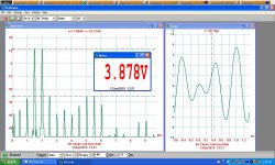
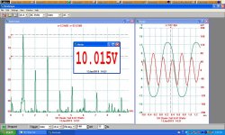
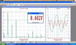
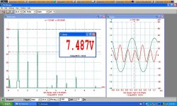
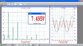
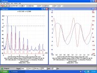
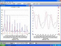
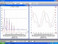
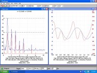
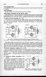
Here are some of the many results of the self inverting output circuit with PP 6V6s connected as in the Oddwatt. In this case the driver is a simple triode connected 6AU6. There is no NFB at all, these results are for the bare bones circuit. In no case could the circuit deliver more than about 1/2 what is possible while using a proper driver stage.
I did a summary of results that covered many of the earlier circuits back to the late 1930s, just gotta find it. I'll post more later.🙂
I did a summary of results that covered many of the earlier circuits back to the late 1930s, just gotta find it. I'll post more later.🙂
Attachments
-
 5H Choke Tail 2-Tone One Watt.JPG171.8 KB · Views: 62
 -
 5H Choke Tail 6.67 Watts.JPG176 KB · Views: 57
 -
 5H Choke Tail 5 Watts.JPG170.6 KB · Views: 60
 -
 5H Choke Tail 3.75 Watts.JPG167.7 KB · Views: 58
 -
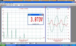 5H Choke Tail One Watt.JPG168.9 KB · Views: 62
 -
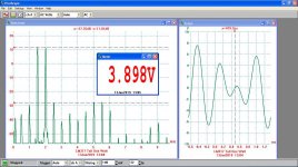 LM317 Tail 2-Tone One Watt.JPG346.5 KB · Views: 66
 -
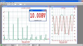 LM317 Tail 6.67 Watts.JPG357.9 KB · Views: 169
 -
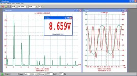 LM317 Tail 5 Watts.JPG319.5 KB · Views: 175
 -
 LM317 Tail 3.75 Watts.JPG342.2 KB · Views: 173
 -
 LM317 Tail One Watt.JPG311 KB · Views: 192
Hi, Others results differ however, not to get into arguements. The class A stage show is indeed limited to about 35% of the input DC power. That's a given. Using various tube combinations up to KT120s you can get as much as 40 wrms output. In various sizes the amps are a comercial product and work well. But you still need to realize they are class A and that does limit the output. With a conventional splitter and bias arrangement you can get a lot more output...if that is what you want. Many folks don't need it and like the forced class A operation. Different strokes for different folks.🙂
But much easier to get both power & fidelity while running Class A with several different versions of ordinary phase inverters.🙂
Sparton 8549 Consumer Receiver PP 6V6s
I looked at several attempts at the Self Inverting PP power stage, this is another from the mid-40s. The cathode resisters are 270R each. The performance is better than those circuits with only a single cathode resister. But still needs help. I tried limited NFB to further check performance. All here for your curiosity. Or not!!🙂
I looked at several attempts at the Self Inverting PP power stage, this is another from the mid-40s. The cathode resisters are 270R each. The performance is better than those circuits with only a single cathode resister. But still needs help. I tried limited NFB to further check performance. All here for your curiosity. Or not!!🙂
Attachments
-
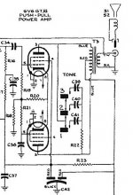 Sparton 8549 Output Stage 7H.jpg79.6 KB · Views: 100
 -
 self inverting pp 6v6 amplifier sparton 8549 version.JPG41.9 KB · Views: 88
 -
 Self Inveritng Stage J.jpg250.7 KB · Views: 63
 -
 Self Inveritng Stage I.jpg252.2 KB · Views: 128
 -
 Self Inveritng Stage H.jpg252.3 KB · Views: 121
 -
 Self Inveritng Stage G.jpg251.5 KB · Views: 126
 -
 Self Inveritng Stage F.jpg244.9 KB · Views: 125
 -
 Self Inveritng Stage E.jpg239.8 KB · Views: 152
Some Miscellaneous Additional Info
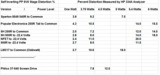
I found several examples of the Self Inverting Power Stage. Here is more info & a results table of some of the tests setup. I tried to get better results by terminating some of the tails on a negative supply, that didn't help much.
All the results are real measurements on the bench, not simulations. Test equipment included an HP 334A THD Analyzer, a MetraHit 29S Precision DVM & Wattmeter &Pico Technology 3224. The PicoTech Scope/Spec A has 12-bit resolution so dynamic range is 72 db, sufficient for most vacuum tube work.
A very old example of the circuit runs a pair of 117L7GTs at WW2 time. Probably leftovers in a tube stash, parts were scarce.
Attachments
-
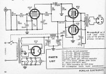 PP 6V6 Self Inverting Amplifier p48 Popular Electronics.jpg59.8 KB · Views: 89
 -
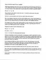 Improved Self Inverting PP Amplifier Notes 2017.jpg434.3 KB · Views: 79
 -
 RDH4 p 585 30C Self Inverting Push Pull.jpg455.6 KB · Views: 95
 -
 Self Inverting PP 6V6 Distortion.jpg118.6 KB · Views: 80
 -
 6AD7G Copy p2 20C.jpg277.2 KB · Views: 87
 -
 117L7GT PP Amplifier with Self Inversion.jpg494 KB · Views: 115
Improved ? Self Inverting Stage
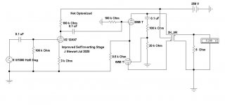
I found this on the iNet a while ago. But haven't tried it. Looks like it might solve a problem, I found it was impossible to drive the second grid far enough negative.This circuit looks like it would do that. But the drive to the 2nd grid would have all the distortion from the other side. Still worth a look for the sake of curiosity.🙂
I found this on the iNet a while ago. But haven't tried it. Looks like it might solve a problem, I found it was impossible to drive the second grid far enough negative.This circuit looks like it would do that. But the drive to the 2nd grid would have all the distortion from the other side. Still worth a look for the sake of curiosity.🙂
Attachments
Learned Paper Describes Self Inverting Power Stage
For the mathematically inclined & others this a good description of what is required to get the best results. The bottom line is a very large impedance in the cathode tail.
The LM317, an NFET or Choke should satisfy that requirement & they do in theory. But in practice the results are less than perfect. A much better result is usually possible by proceeding the power stage with a proper phase inverter.🙂
The circuit was patented by the BBC in the UK.
Attachments
- Home
- Amplifiers
- Tubes / Valves
- Simple power amp