As a still DOS user, I have installed in my AMD486, the well known
TSTHost 143C. All that has been using it, will know that the program uses the
system speaker to generate somel tones when a colleague is calling, when it
connects to a BBS, etc., or some DOS games uses that speaker to play some
simple musics. Normally, the sound from this speaker is tiny, and has no way
to be amplified, and isn't possible (via soft or hard) to adjust the volume
from it.
I dissamble some old PC speakers (Two white boxes containing an oval
4R 3W loudspeaker. I don't want to use the original amplifier because it is
linear IC, and tones from the PC mother are digital 5Vpp squeare waves, so
it will be severly overloaded. So, I discard all the board containing such
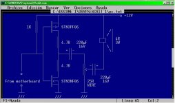
amplifier, and designed this easy MOSFET "digital amplifier". It only
consists in a complementary pair wired as a inverter, the transistor can be
any N and P complemetary MOSFET's. I used STN3PF06 and STN3NF06, but may be
any other (IRF120 and IRF9120, for example).
Resistors in the drain in each MOSFET attenuates the spikes during
starting the PC and prevents cross conduction, and destruction of the output
transistor in case of wrong connection in the 4 pin connector at the mother-
board. The first 220µF 16V electrolyitic capacitor isolates DC at the middle
point to the 25R wire pot using normally in older car radios to fader between
front and rear speakers, and has a stop (no wire) at the fully counterclock-
wise stop, acting as a switch. Second cap provides isolation to the moving
coil returned to the 12V bus, because in this way, noise when no using is
less than when returned to ground, but it can be tested by each maker.
Finally, the 1K bias the amplifier to low state in the drain node, and
provides a DC path for the transistor located in the motherboard (a 2SC945
or 2SC1815 transistor amplifing the out of the sound generating chip embedded
in a jungle IC, but that emulates the classic 8253 chip).
It isn't necessary to modify anything in the mother. But, I replace
such transistor (BJT) by a MOSFET 2N7000, and eliminate the 33R usually in
series to the collector, and replace with a small ferrite bead. So I have a
bigger DC output swing at the drain of the 2N7000, and applied directly to
the gates of our complementary pair. And also I removed old 1K base limiting
resistor, and replace it with the 33R above mentioned. I did it in an old UMC
chipset with a AM486 CPU.
In the 4 pin there are two 5V pin (ussualy, but it can be different in
different motherboard manufacturers, a ground pin (0V), and the audio out.
Caution to not connect the input of the amplifier to any of the 5V pins,
because in case of not to have the 4.7R in its drains, and transistors being
class A biased, will be overheated and destroyed.
It isn't necessary to attach any heat sink to the transistors. I use
the above mentioned, as they are SMD devices, the only heat sink is a small
and short PC track. As it operates digitally (between +12V to 0V and vice
versa very quickly), they don't get hot.
The power output is low, about few watts, but sufficient to be heared
from large distances and very loud. Also the power consumption is very low,
especially when no audio output because any one of the transistor is off, so
no current drawing in them. Only the 1K draws 5 mA, and can be further reduced
increasing its ohmic value.
Enjoy !!!
TSTHost 143C. All that has been using it, will know that the program uses the
system speaker to generate somel tones when a colleague is calling, when it
connects to a BBS, etc., or some DOS games uses that speaker to play some
simple musics. Normally, the sound from this speaker is tiny, and has no way
to be amplified, and isn't possible (via soft or hard) to adjust the volume
from it.
I dissamble some old PC speakers (Two white boxes containing an oval
4R 3W loudspeaker. I don't want to use the original amplifier because it is
linear IC, and tones from the PC mother are digital 5Vpp squeare waves, so
it will be severly overloaded. So, I discard all the board containing such
amplifier, and designed this easy MOSFET "digital amplifier". It only
consists in a complementary pair wired as a inverter, the transistor can be
any N and P complemetary MOSFET's. I used STN3PF06 and STN3NF06, but may be
any other (IRF120 and IRF9120, for example).
Resistors in the drain in each MOSFET attenuates the spikes during
starting the PC and prevents cross conduction, and destruction of the output
transistor in case of wrong connection in the 4 pin connector at the mother-
board. The first 220µF 16V electrolyitic capacitor isolates DC at the middle
point to the 25R wire pot using normally in older car radios to fader between
front and rear speakers, and has a stop (no wire) at the fully counterclock-
wise stop, acting as a switch. Second cap provides isolation to the moving
coil returned to the 12V bus, because in this way, noise when no using is
less than when returned to ground, but it can be tested by each maker.
Finally, the 1K bias the amplifier to low state in the drain node, and
provides a DC path for the transistor located in the motherboard (a 2SC945
or 2SC1815 transistor amplifing the out of the sound generating chip embedded
in a jungle IC, but that emulates the classic 8253 chip).
It isn't necessary to modify anything in the mother. But, I replace
such transistor (BJT) by a MOSFET 2N7000, and eliminate the 33R usually in
series to the collector, and replace with a small ferrite bead. So I have a
bigger DC output swing at the drain of the 2N7000, and applied directly to
the gates of our complementary pair. And also I removed old 1K base limiting
resistor, and replace it with the 33R above mentioned. I did it in an old UMC
chipset with a AM486 CPU.
In the 4 pin there are two 5V pin (ussualy, but it can be different in
different motherboard manufacturers, a ground pin (0V), and the audio out.
Caution to not connect the input of the amplifier to any of the 5V pins,
because in case of not to have the 4.7R in its drains, and transistors being
class A biased, will be overheated and destroyed.
It isn't necessary to attach any heat sink to the transistors. I use
the above mentioned, as they are SMD devices, the only heat sink is a small
and short PC track. As it operates digitally (between +12V to 0V and vice
versa very quickly), they don't get hot.
The power output is low, about few watts, but sufficient to be heared
from large distances and very loud. Also the power consumption is very low,
especially when no audio output because any one of the transistor is off, so
no current drawing in them. Only the 1K draws 5 mA, and can be further reduced
increasing its ohmic value.
Enjoy !!!