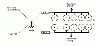
Gordy said:
Nobody said tie them directly. Experience suggests that they should be linked such that there is a dc path, with a low value resistor or small inductance being suitable for the link.
You are correct, nobody used the word directly. BUT, somebody used the words
joining only at the mains (or in this case, at the chassis).
with no mention of a resistive component. I would think specificity would be important in this case.
I'm not trying to be argumentative, just trying to get to the bottom of it...
Gordy said:And nobody disagreed with you.
I'm reacting to Andrew's non-response through reiterating his original comment inferring some higher authority. Saying nothing would have been better, both comments would stand as food for thought.
Mike.
Oh, I forgot to point out that this is a very interesting topic that there are many interesting questions.
Mike.
Mike.
I cannot see how this conclusion was reached.But that's not what he said or was implied
I never implied any high(er) authority.I'm reacting to Andrew's non-response through reiterating his original comment inferring some higher authority.
I see no point in trying to ram my opinion down your throats. It's only liable to choke one.
Similarly, there is little advantage in simply repeating what "I would do".
Tell us the alternatives and how these alternatives solve the loop problem, if one exists.
Then the enquirer can decide for himself/herself.
Because of all grounds should have identical potential.
I can drop it out if any troubles will arrive, but they won't i think.
I can drop it out if any troubles will arrive, but they won't i think.
Hi,
remove the control/power return from the audio ground.
It will contaminate the clean ground.
remove the control/power return from the audio ground.
It will contaminate the clean ground.
why? 😕FaTTy said:Because of all grounds should have identical potential.
regards
Jürgen
AndrewT said:I cannot see how this conclusion was reached.
I never implied any high(er) authority.
I see no point in trying to ram my opinion down your throats. It's only liable to choke one.
Similarly, there is little advantage in simply repeating what "I would do".
One last comment. I follow every thread that discusses grounding. In most any discussion Andrew weighs in and quotes from the "higher authority I alluded to" Passing on useful information to those who ask. I have no issue with alot of it. I don't know the distinction between ramming and being an outspoken source.
My point of view is different and it would be interesting if I pointed out a difference and someone tried it and got back with feedback either way. Hasn't happened yet, didn't happen this time.
Whatever. Mike.
juergenk said:
why? 😕
regards
Jürgen
Doing this i had minimum hum level in my amp. I think i don't be able to explain this from science point.
I also see no reason to join signal ground to the chassis or PSUs ground in any way whatsoever.
IMO ideally you'd keep signal ground separate from PSU ground, I see no reason why you couldn't keep left/right grounds separate (but I wouldn't bother), but I can see some potential merit in not having all the input sources grounds constantly connected - this seems to be the "dodgiest" aspect of this design to me, but I can definately see why it'd make it more complicated.
IMO ideally you'd keep signal ground separate from PSU ground, I see no reason why you couldn't keep left/right grounds separate (but I wouldn't bother), but I can see some potential merit in not having all the input sources grounds constantly connected - this seems to be the "dodgiest" aspect of this design to me, but I can definately see why it'd make it more complicated.
- Status
- Not open for further replies.
- Home
- Amplifiers
- Solid State
- Simple passive preamp. Neen some help in grounding.

