At 320V, I did not see any plate or screen glow. I may try ramping things up later to see when they start to become upset.
CEO said we could go home early, LOL. As long as we can still come back on Monday....
Plates started glowing at 330V across the tube after a minute or less. 320V is actually right on the edge...after a few minutes it is possible to see a very dull glow. All four glowed the same, which is nice I guess. No evidence of screen glow (still wired directly to B+).
According to another spec I found, the EL84M (6P14P-EP) seems to have more transconductance for a given operating point than a normal EL84. This may be why they run hot even though the plates are supposedly rated for 400V max.
Need to find my half-baked Bevois Valley amp. The JJs must be with it.
Bass is a little better with the proper taps being used. Need to try NFB next.
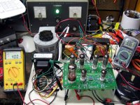
So here we are running at 400V B+, which is a little above line level on the variac. The screens are on the bench supply fixed at 250V. No plate or screen glow was noted. Had to take care of other things, so that's as far as I got. EL84s have 386V across them.
Attachments
Well I got the remaining socket for my board and the diodes. I was hoping to have it up and running tomorrow but I forgot about going to visit my brother for his birthday. So I will be busy. Hopefully there will be a hardware store near by so I can pick up some nuts and bolts to hold everything to the chassis. There isn't a whole lot left to do besides do some wiring. I was going to shoot a photo of the board but Russ has a few up. Once I start the wiring I will take a couple of photos to verify I have it all correct. I have opted to place the resistors on top of the board and the capacitors below. I also decided to use the socket savers to raise everything up a bit and keep the resistors away from the top plate.
I was asked to provide some photos that show the connections to the board. I got the board wired back up. I will photograph the actual connections tomorrow.
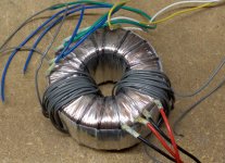
There was some concern that the Antek 1T200 would not power this amp without getting hot. I connected the amp up with load resistors and a signal generator, and ran it at full power while Lost was on TV. After Lost was over, I cranked some techno through the speakers at just below clipping, for nearly an hour. The photo shows the power transformer in my hand, while the amp was runnung. It was mildly warm.
There was some concern that the Antek 1T200 would not power this amp without getting hot. I connected the amp up with load resistors and a signal generator, and ran it at full power while Lost was on TV. After Lost was over, I cranked some techno through the speakers at just below clipping, for nearly an hour. The photo shows the power transformer in my hand, while the amp was runnung. It was mildly warm.
Attachments

Gotta love toroids. I have a shopping cart at Antek with some iron in it. Haven't pulled the trigger, though. Spent too much money lately as it is. Dollar for VA, you can't beat their prices. Makes Hammond look outrageous. Too bad they don't put any 5V windings on them. Must be a reason for it...all their toroids seem to have pairs of primaries and secondaries. Maybe it simplifies design/assembly somehow.
The JJ EL84s came today, but I am too tired to play with tubes tonight. I did get some good looking results using the Sovtek EL84Ms. It required finding the best pair out of the remaining three tubes and powering the amp with the bench supply. I think if I can clean-up the PSU it will fair better.
This is what I did to get 5V out of my Antek PT.Too bad they don't put any 5V windings on them. Must be a reason for it...all their toroids seem to have pairs of primaries and secondaries. Maybe it simplifies design/assembly somehow.
This is what I did to get 5V out of my Antek PT.
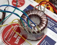
I needed two 5 volt windings for my dual Simple P-P amp, and I am much to lazy to do it right, so I just wrapped the two new secondaries through the core using ordinary hook up wire. I think my particular transformer (a 4T360) needed 13 turns for 5 volts. I can post a picture tonight.
Makes Hammond look outrageous.
I don't think that you will want to hold a Hammond in your hand after it has been running near its maximum ratings for a few hours either!
Too bad they don't put any 5V windings on them. Must be a reason for it...all their toroids seem to have pairs of primaries and secondaries.
I am of the opinion that whoever is actually designing these transformers has no clue about what is really needed for a tube amp. I sent John an email explaining what the tube world really needed, and even included some Hammond part numbers, about 2 years ago and never got a reply.
They recently added the 4TK400 which is 2 steps in the right direction, and a step in the wrong direction. The transformer is still useless as is. They added a 5 volt winding (good) and added two 70 volt taps, one on each side of the HV CT (excellent for regulated bias supplies), but removed one of the 6.3 volt windings. OK the transformer is rated for 400VA, big enough to run a monster sized stereo tube amp, but the total current rating for the single 6.3 volt winding is only 4 amps. That isn't even enough to light two big sweep tubes. And yes the spec sheet on their web site is WRONG! It doesn't match the transformer that you get.
Oh, so the 4TK400 doesn't have two 6.3V windings? They really need to update that. I was planning to wrap my own 5V winding with hookup wire. What about the 1T200 and the others? Still dual 6.3?
Even, that sounds like a lot of un/rewinding. 🙂
Even, that sounds like a lot of un/rewinding. 🙂
I know it's a little wasteful and brings the cost up, but could you use two 1T200's for the dual Simple P-P amp?
I guess at that point you'd pretty much be making two monoblocs.
I guess at that point you'd pretty much be making two monoblocs.
I noticed that as well and I bought one based on their spec. The mod I did works so it's no big loss. It actually gave me a chance to get my hands "dirty" and learn something about toroid PT in the process.And yes the spec sheet on their web site is WRONG! It doesn't match the transformer that you get.
I know it's a little wasteful and brings the cost up, but could you use two 1T200's for the dual Simple P-P amp?
Well, I have two of the 1T200's, and yes I could run two 6CW5 boards that way, but I have something much bigger in mind. I am planning to wire two boards to one 4T360 stuff them with JJ EL84's and put them INSIDE a small box. There will either be one very loud amp, one big bang, or a major meltdown. I breadboarded one channel and saw it work for maybe 5 minutes last December. I then drew up all of the plans while up north without any of the stuff in front of me. I have been building this "thing" in wood shop class on Thursday nights. The other students have been indifferent about my tube amps, but they are amused by this "thing" since no one can visualize the completed design. It's too late to turn back now...
What about the 1T200 and the others? Still dual 6.3?
I don't really know since I have had my pair for at least a year. Got them for a circlotron experiment that ended badly. I blew up a few 6AS7's, but I have at least a hundred, and I experimented on some really crusty ones with loose bases.
This is what I did to get 5V out of my Antek PT.
OK, here is my rude and crude version. Electrically this is OK as long as the wire used can handle the voltage (at least 400) and current (2 amps per winding with 5AR4's. I haven't decided whether to hide the toroid under a cover, or let it be seen. Either way I am going to need to re do the wingings to make them prettier, or make them fit in a can.
Even, that sounds like a lot of un/rewinding.
I would leave any existing windings intact. Why disturb them. I plan to add any new windings right on top of the existing mylar covering, then wrap several layers of Kapton tape over them.
Attachments
Pictures as promised:
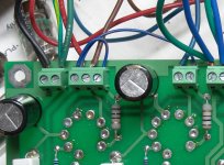
First photo, shows the detail of the interconnection on the Antek transformer.
Note that the center white and center yellow wires are twisted together and connected to the T1-RED-YEL connector on the PC board. This is the center tap on the HV winding. The remaining yellow wire and the remaining white wire go to the outer T1 red terminals on the PC board. It does not matter which wire goes to each terminal.
Note the pairing of the green and blue wires. Getting this wrong SHOULD blow the fuse provided that there is a fuse and it is no bigger than 2 amps, Otherwise it will blow the transformer. Not sure, just use the green wires and tape up the blue ones.
The primary detail is not shown. The two red wires are connected together, and the two black wires are connected together.
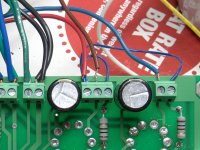
The second photo shows the connection of the white and yellow wires.
The third photo shows the connection of the green and blue wires. Do a better job of avoiding bare wires than I did. I only hooked this up to take pictures and some of the other wires are worse.
First photo, shows the detail of the interconnection on the Antek transformer.
Note that the center white and center yellow wires are twisted together and connected to the T1-RED-YEL connector on the PC board. This is the center tap on the HV winding. The remaining yellow wire and the remaining white wire go to the outer T1 red terminals on the PC board. It does not matter which wire goes to each terminal.
Note the pairing of the green and blue wires. Getting this wrong SHOULD blow the fuse provided that there is a fuse and it is no bigger than 2 amps, Otherwise it will blow the transformer. Not sure, just use the green wires and tape up the blue ones.
The primary detail is not shown. The two red wires are connected together, and the two black wires are connected together.
The second photo shows the connection of the white and yellow wires.
The third photo shows the connection of the green and blue wires. Do a better job of avoiding bare wires than I did. I only hooked this up to take pictures and some of the other wires are worse.
Attachments

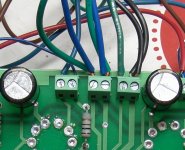
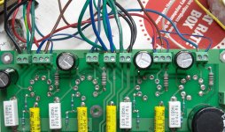
First picture, overall picture of OPT hookup.
Second picture shows the Left OPT, which is on the right since the board is flipped over. The thin Blue wire connects both screen grids up to the red OPT wire which selects pentode mode. Use a better quality wire since it handles 400 volts. The Blue, Brown and Red wires are the OPT primary. The connector on the left is for the feedback and is connected to the OPT secondary. The thick Green and Black wires come from the OPT. The thinner green and black wires go to the left speaker terminals.
The third picture shows the right OPT. The colors and connections are the same as the other channel with one exception. The feedback wires on the right channel have the black wires closest to the edge of the board (on the left). THe left channel has the black and green wires reversed (black on the right)
Attachments
Speaking of wiring...this is embarrassing. So I was wiring one of those Triad C-14X chokes when I noticed I made an error when I initially wired up the board. That's what happens when I do these things late at night. Long story short, R1 was effectively shorted which is why: a) I had a lot of 120Hz buzz getting into the audio; and b) why I was getting more B+ than George was. With the choke in place and R1 pulled, things are much more sane and quiet:
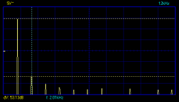
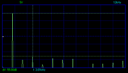
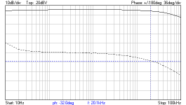
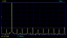
650VAC yields 325V B+, which puts about 310V across the tubes. I also installed the JJs tonight and between the two I got some good results on the bench. My left channel has more even harmonics than the right. Swapping output tubes has no effect, so I am guessing the resistors in the "concertina" phase splitter are not well matched. I didn't check them during assembly. These spectra are at 1W of output. The frequency response is at about 3W (solid line is the response and the dotted line is the phase).
Edit: these are with the JJ EL84 tubes and both channels are driven.
Attachments
Last edited:
Well just like you warned I some how mixed up the green and blue wires. Ooops and I only had one fuse left. So tomorrow when I am out I will grab some more fuses. I think I will just tape off the blue wires like you mentioned. Otherwise all of the wiring is correct. It is like a bowl of spaghetti under my chassis. I am already planning to redo it as it is a huge pain in the *** to work on.
Well I think that the 6.3volt winding is shot. I found another fuse and redid the filament wiring and decided I would measure everything to see if it all checks out. The fuse didn't instantly blow like it did before but my readings seemed off for the 6.3volt winding. I had 209 vac on the t1-red terminals and around .1 vac on the t1-grn terminals. I have the green wires going to t1grn and the blue wires tied and taped together.
I had 209 vac on the t1-red terminals and around .1 vac on the t1-grn terminals.
Are you measuring the voltage with one meter lead connected to ground? If so that would be a completely normal reading. Put some tubes in the board and see if they light up.
- Status
- Not open for further replies.
- Home
- More Vendors...
- Tubelab
- Simple P-P "beta builders" thread