Bonsai said:With your latest circuit, PSSR will remain unchanged. What will improve is the output noise because you have filtered the noisy Zener.
Re the use of a big output cap. I prefer to use as big a cap as possible to keep the output impeadance low - especially at higher frequnceis where the open loop gain of the op-amp reduces. However, you have to watch that you do not introduce a pole in the loop with a low ESR cap - so this is where you have to try th e caps out to make sure the regulator remains stable.
I think some of the results we are getting in the sims are probably not acheivable (one sim showed better than -200dB!), but you should be able to get a a good, improved result.
I agree completely. the almost ideal world of the simulator can be very deceiving. To me is only a playground to test some ideas before reaching for the soldering iron. I'm not sure if I should allow myself to think that a circuit that simulates twice better than another will actually be better in real life too. Sometimes it is, and it's a matter of trying it out.
The zener noise isn't properly simulated... I'll see what I can do about that.
analog_sa, do you mean that your Jung implementation did not sound good? I wonder why we hear often that sound gets worse as soon as an opamp enters the equation. Well, someone with better listening skills than me will have to be the judge of this one. I listened to it this morning but cannot tell the difference between this and the few others I have

salas said:
I would be glad to make one and subjectively ***** it when its final, and maybe there is a PCB.
salas, that would be great, I trust your ears anytime over mine. My wife thinks I'm a bit hard of hearing, which definitely helps when she dispatches house chores
")
ikoflexer said:
analog_sa, do you mean that your Jung implementation did not sound good? I wonder why we hear often that sound gets worse as soon as an opamp enters the equation.
Jung/ALW was my reference until last week. Since then i have built and started listening to something similar to the regulator syn08 proposed in the other thread. CCS is a 317 and i am not using the "weird" cap from his circuit. Opamp is 627. I like the sound better than the Jung in practically every respect. It is very similar to your circuit and i don't expect it to perform differently in any meaningful way.
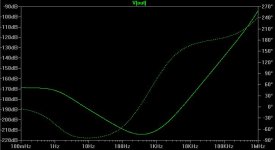
Btw, R15 in your second circuit will work as intended. Now the zener noise is filtered and the opamp inputs get almost equal impedance in both ac and dc. I asked if you have simulated the performance of the CCS alone, ie impedance against frequency.
Not sure if any of the above has any real effect on sound or whether the simulations have any value. Circuit implementation will quite possibly determine the actual parameters.
analog_sa said:
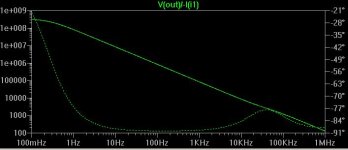
I asked if you have simulated the performance of the CCS alone, ie impedance against frequency.
Please show me a sketch of the schematic, parts, values, and I'll run the sim, no problem.
analog_sa said:
It is very similar to your circuit and i don't expect it to perform differently in any meaningful way.
Not at all. If you noticed, my circuit does not use a "follower" as parallel element, but it tries to provide some extra loop gain there. This means a N channel MOSFET instead of P channel and the opamp is flipped. Such a configuration provides at least 6dB of improvement in both output impedance and line regulation, at the penalty of a small reduction in the phase margin.
OTOH, OPA627 is not the best in such an application. I think I already mentioned, it may not have enough +/- output swing to correctly drive the MOSFET. Also, the bandwidth of OPA627 is limited, leading to suboptimal HF performance. LT1115, THS4031 or even LME49710 will do much better. Even the noise will be better.
The "weird" cap provides even more loop gain, but then you don't need to like it.
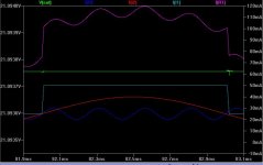
Here's another result, the transient response to three parallel active loads I1, I2, and I3
I1 PULSE(25m 50m 0 10u 10u 1m 2m)
I2 SINE(25m 15m 500)
I3 SINE(25m 5m 4k)
All together give a current as shown in I(R1), and the regulator response in V(out).
I1 PULSE(25m 50m 0 10u 10u 1m 2m)
I2 SINE(25m 15m 500)
I3 SINE(25m 5m 4k)
All together give a current as shown in I(R1), and the regulator response in V(out).
Attachments
ikoflexer said:
Please show me a sketch of the schematic, parts, values, and I'll run the sim, no problem.
I meant the CCS part of your regulator.
syn08 said:
Not at all. If you noticed, my circuit does not use a "follower" as parallel element,
Oops. Sorry, should keep my eyes open. I completely agree that the ths4031 is a great opamp and probably also more suitable for this application but the ones i have are currently in use in one of my dacs and i am a bit reluctant to desolder them. Will order some more and try them out.
analog_sa said:
I meant the CCS part of your regulator.
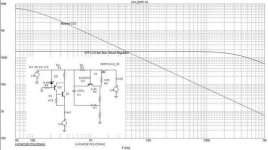
I'm at a loss. Can you write it as V(part_number)/I(part_number) ? I just don't know which CCS you're talking about, sorry.
ikoflexer said:
I'm at a loss. Can you write it as V(part_number)/I(part_number) ? I just don't know which CCS you're talking about, sorry.
Attachments
ikoflexer said:Ah, oh,
BTW, does anyone have the Stax regulator schematic handy? Could not find it yet.
Not sure what you are doing in your sims, but for measuring the impedance at a node you need to set all other AC voltage and current sources to zero, then inject a 1A AC current in the node you want to measure the impedance at and read the voltage across this current source. This voltage is numerically equal to the impedance at the injection node. No calculations are required. Sweep the frequency, of course.
Uchi Deshi said:
In Anno Domini 2009 I wouldn't touch that thing with a stick. Only one quick observation: the reference is a JFET constant current source and a resistor
 28 years passed since 1981 and we have low noise references today... And the noise current at the current source output... don't even think about
 - Status
- This old topic is closed. If you want to reopen this topic, contact a moderator using the "Report Post" button.
- Home
- Amplifiers
- Solid State
- Simple opamp/mosfet shunt regulator