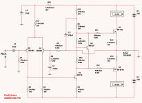
richie00boy said:R5 and R15 should be the same value?
no!R5 and R15 at curent value is ok!,I had make some Simulation
..THD&phase offset is better than them at same value..
🙂
What is the point of r3? It doesnt do anything at all.
Why not use a current mirror for the LTP. It will almost certainly lower THD and increase slew rate.
Doug Eleveld
Why not use a current mirror for the LTP. It will almost certainly lower THD and increase slew rate.
Doug Eleveld
deleveld said:What is the point of r3? It doesnt do anything at all.
Why not use a current mirror for the LTP. It will almost certainly lower THD and increase slew rate.
Doug Eleveld
Hi,deleveld:
somebody suggest R3 should be add,they said it will make the circuit work more balance...So I do..
as the title named "simple",this is the basic circuit of the complecity struture you say so..least device can be gain more fidelity..I think
and also suitable for the people who hated trouble like me,because it is much easy to do and don't need more component..
thanks!
Hi Darkhorse,
Don't forget the output stage Zobel network that will be necessary to stop a real world construction of this amplifier from chasing its tail.
Cheers ......... Graham.
Don't forget the output stage Zobel network that will be necessary to stop a real world construction of this amplifier from chasing its tail.
Cheers ......... Graham.
Graham Maynard said:Hi Darkhorse,
Don't forget the output stage Zobel network that will be necessary to stop a real world construction of this amplifier from chasing its tail.
Cheers ......... Graham.
Thank you!Mr.Graham Maynard.
the output stage zobel network must needed!I miss..
and also input stage need shunts a small capacitor 100pF..
so sorry for my untight manner!forgive me please.
from now on,the schematic diagram I draw will be more serious..
happy!

DarkHorse said:
Hi,deleveld:
somebody suggest R3 should be add,they said it will make the circuit work more balance...So I do..
as the title named "simple",this is the basic circuit of the complecity struture you say so..least device can be gain more fidelity..I think
and also suitable for the people who hated trouble like me,because it is much easy to do and don't need more component..
thanks!
Whoever told you that is wrong 🙂 It *looks* more balanced, but in electrical terms it is not. There is no way you can get the currents in each leg of the LTP even remotely close with two resistors like that.
Take out R3 and then adjust R2 until the current flowing in each leg of the LTP is as close to equal as you can get it at idle.
You also need a small (22-220pF, determine experimentally) capacitor across Q3 base-collector otherwise you will see oscillation when you build it.
And I really think you need to make R5 and R15 equal. Simulation results are not always real 😎
Q1 would benefit from a small base resistor.
A diode needs to be added from the collector of Q4 to the B+ rail to prevent gate damage.
A diode needs to be added from the collector of Q4 to the B+ rail to prevent gate damage.
DarkHorse said:somebody suggest R3 should be add,they said it will make the circuit work more balance...
I believe this is a common mistake. People think because it looks on paper to be more balanced, then it is. In the books I have read and amplifiers I have built they don't have a R3.
My understanding is it will still work with R3 but it will have more distortion.
EIDT: oops, a bit slow in hitting the submit button. 😉
about R3
I've heard it 'equalizes' R*Cmiller time constants in LTP, sounds sensible but I'm not sure about real profit.
I don't know if I am right, but this amp seems to me low open loop gain and no frequency compensation,
.... aaghh someone suggested a zobel-don't know if this would be enough comensation
I've heard it 'equalizes' R*Cmiller time constants in LTP, sounds sensible but I'm not sure about real profit.
I don't know if I am right, but this amp seems to me low open loop gain and no frequency compensation,
.... aaghh someone suggested a zobel-don't know if this would be enough comensation
hello,everybody:
thanks you reply and suggest..
about R3,I think I will reply you after I make some simulation about it;
about R5 and R15 should be the same value:
I have study many schematic diagram on book,many of the amp's
bootstrap section didn't let the two resistor in same value,sure you and I know the nelson pass's "ZEN" has,but have you see "JLH" BJT version,two resistor didn't in same value,is it?
I don't know why they have diffient,But I know the bootstrap is positive feedback,intent to boostup the volt-level,let out waveform come to more equally,so I don't think Rup/Rlow=1..
regards,
WINCO
I have a doubt with this circuit diagram:
should I shunts a 100nF capacitor to Q4 as buffer?
from result of my multisim2001,larger value(10uF) may
casing more distrotion..
any help with the buffer capacitor?
how much value is suitable?
best regards!
😕
should I shunts a 100nF capacitor to Q4 as buffer?
from result of my multisim2001,larger value(10uF) may
casing more distrotion..
any help with the buffer capacitor?
how much value is suitable?
best regards!
😕
You guys don't have a clue.
"larger value(10uF) may
casing more distrotion.."
The suggested Miller cap was 22~220pF, 10µF is only 500,000 times the value recommended.
Multi Sim will not tell you how big to make this cap, it can't. You have to build it and they find the actual value from the actual layout with the actual parts.
"about R5 and R15 should be the same value:"
You could replace R15 with a diode if you wanted to, it does not have to be the same value as R5.
"R3"
Would need to be the same complex impedance that is seen at the base of Q3. Since this varies with frequency, temperature, and load, it is never going to happen.
hi,djk:
you said the buffer capacitor value should be about 220pF,
is it too small?I had seen many circuit diagram of AMP,most of them signed about 100nF..
now I know the "simple" isn't reducing device quantity,so many
unsafe factor in my schematic..haha..
as somebody said:"it is seemed simple,infact it need more patience to ensure it can working well"

10uF across Q4 to shunt/lower impedance is OK. However, I was talking about Q3. Here 22-220pF will be required. As djk says, you will have to build it to determine the value.
Re: That thopologie sounds very good.
hi,richie00boy:
oh,I am mistake the means of djk's says,thanks for you suggestion!
I will post a currect schematic tomorrow..
hi,Mr.Carlos:
I think so,
I believe this amplifier will sounds good with your skilled work!
best regards!
WINCO
😉
richie00boy said:10uF across Q4 to shunt/lower impedance is OK. However, I was talking about Q3. Here 22-220pF will be required. As djk says, you will have to build it to determine the value.
hi,richie00boy:
oh,I am mistake the means of djk's says,thanks for you suggestion!
I will post a currect schematic tomorrow..
destroyer X said:This amplifier is a big promiss to be wonderfull.
Carlos
hi,Mr.Carlos:
I think so,
I believe this amplifier will sounds good with your skilled work!
best regards!
WINCO
😉
My mistake, when you said "should I shunts a 100nF capacitor to Q4 as buffer?" I thought you were talking the Miller cap which goes from the base of Q3 to the emitter of Q4.
A bias shunt from the emitter to collector of Q4 could be in the range of nothing to several hundred µF.
Too small of a cap and the signal can modulate the bias, if a large cap is used it must be of very high quality or the treble will suffer.
I frequently use 2.2µF with about 10mA in the VAS.
A bias shunt from the emitter to collector of Q4 could be in the range of nothing to several hundred µF.
Too small of a cap and the signal can modulate the bias, if a large cap is used it must be of very high quality or the treble will suffer.
I frequently use 2.2µF with about 10mA in the VAS.
good bay,everybody:
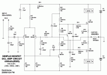
I have modify the circuit diagram according to what we had refered,I chang the PS voltage from +/-24V to +/-35,this can casing the amp output more linear in high voltage supply.and you
can use your transformer with 2*AC18V~25V to get +/-DC25V~35V.
you need to meter the output terminal's voltage is 0V through adjusting RP1(set to middle at first) and RP2(set to MAX at first).
with high voltage power supply,it's output power from about 20W(+/-24V,8ohm) up to 42W(+/-35V,8ohm),more suitable for household audio device,is it?
note:Q4 should contact to heatsink where is near to Q5 or Q6,this is good to Iq stabilization.If your loudspeaker impedance is 4Ohm,I suggest use lower voltage supply(=<+/-30V).
any comment please?
happy!
WINCO
Attachments
- Status
- Not open for further replies.
- Home
- Amplifiers
- Solid State
- Simple OCL AMP

