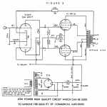
I'm building the attached design into a recently cleaned out Magnavox console amplifier. How would I adjust the input circuit before the 12ax7 with the addition of a 100k volume pot? I've got an idea but I want to make sure it's not way off since I'm just learning and this is only my second build. Detail is appreciated, I learn more from a single question like this than hours spent reading tomes on design and theory, thanks!
Attachments
Cut the left end of the 10k grid resistor, and connect that end of the 10k to the pot wiper.
Connect the bottom terminal of the pot to ground, and connect the top terminal of the pot
to where you cut the 10k from.
When you turn the shaft of the pot full CCW, the bottom terminal is the one that is shorted
to the wiper (middle terminal).
Connect the bottom terminal of the pot to ground, and connect the top terminal of the pot
to where you cut the 10k from.
When you turn the shaft of the pot full CCW, the bottom terminal is the one that is shorted
to the wiper (middle terminal).
Last edited:
Some expense in the original circuit was saved by making the FB resister the bias resister as well.🙂
Cut the left end of the 10k grid resistor, and connect that end of the 10k to the pot wiper.
Connect the bottom terminal of the pot to ground, and connect the top terminal of the pot
to where you cut the 10k from.
When you turn the shaft of the pot full CCW, the bottom terminal is the one that is shorted
to the wiper (middle terminal).
Ok, wasn't sure if I should ditch the 10k grid resistor or not.
Cathode biasing circuit stays the same I would guess?
Is this the Magnavox 93** model? That's the most common PP 6BQ5 one.I'm building the attached design into a recently cleaned out Magnavox console amplifier. How would I adjust the input circuit before the 12ax7 with the addition of a 100k volume pot? I've got an idea but I want to make sure it's not way off since I'm just learning and this is only my second build. Detail is appreciated, I learn more from a single question like this than hours spent reading tomes on design and theory, thanks!
If so, here's a great thread on rebuilding / modding them. There are similar threads on some of their other models.
More Fun With Magnavox: The 9300 Series | Audiokarma Home Audio Stereo Discussion Forums
You might want to read it before using the circuit you posted.
The various Magnavox models, and console amps in general, make great modding platforms. I recently modded a couple of their PP 6V6 versions to use different output tubes. One uses 6N6Gs and the other uses the Russian 4P1Ls.
Last edited:
Ok, so I can probably drop that 470k resistor if using a 100k volume pot ahead of the grid stop resistor (10k)?
Another quick question regarding this end of the circuit. The 100uf 6v cap......I've seen it listed as 16v in modern updates. My regular parts source only had 100v caps for this application. I've got a few 50v versions I chopped out of a Parasound solid state amp (maybe 20 yrs old). Would either of these higher voltage 100uf caps cause a problem here? I hate buying small quantities of 30 cent parts due to the attendant shipping.
Another quick question regarding this end of the circuit. The 100uf 6v cap......I've seen it listed as 16v in modern updates. My regular parts source only had 100v caps for this application. I've got a few 50v versions I chopped out of a Parasound solid state amp (maybe 20 yrs old). Would either of these higher voltage 100uf caps cause a problem here? I hate buying small quantities of 30 cent parts due to the attendant shipping.
I am always willing to learn : Can somebody explain to me
how those input tubes get their DC biasing voltage/current?
I cannot detect how this is done,
how those input tubes get their DC biasing voltage/current?
I cannot detect how this is done,
Isn’t it done using the cathode resistor, the 1K feedback resistor and the grounded speaker winding?
Regards, Gerrit
Regards, Gerrit
So, those DC currents are flowing through the secondary winding of the OT in parallel with the speaker load. I did notice this already but could not believe my eyes.
Lol, guys, if this is not such a great schematic, let me know now! I've only wired up the mains to the transformer and the heaters. I chose it for its relative simplicity and the fact that the power transformer in the unit provided more or less the correct specs. This is the mod I'm using, just with the 12ax7 instead of the 6sl7.
Last edited:
About 1-2 mA at about 1V. No big deal for a speaker.
And by far the most of that thru the OPT secondary.🙂
And by far the most of that thru the OPT secondary.🙂
Lol, guys, if this is not such a great schematic, let me know now! I've only wired up the mains to the transformer and the heaters. I chose it for its relative simplicity and the fact that the power transformer in the unit provided more or less the correct specs. This is the mod I'm using, just with the 12ax7 instead of the 6sl7.
O.K. we were just brainstorming.
But go ahead, make your modifications. 🙂
Looking thru Aspen Pittman's Tube Amp Book we find quite a few guitar & instrument amplifiers used this circuit, both UL & pentode output. Easy to do , low cost & OK in that application.🙂
But you will get perhaps a loud plop at speaker output when switching on the power I think.
Why? At power up the tubes are not conducting until they warm up.
G²
Originally Posted by JoeAlders 
But you will get perhaps a loud plop at speaker output when switching on the power I think.
Look at the numbers, an 8 Ohm loudspeaker VC measures about 6.5 R, the OPT secondary is likely less than On Ohm & perhaps a lot less. Most of a couple of mA will go thru the OPT secondary, the small leftover thru the speaker VC.🙂
O.K. we were just brainstorming.
But go ahead, make your modifications. 🙂
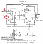
Haha, thanks! Just want to make sure I'm absorbing all I can. So add the volume pot at the arrow here, one side gets the input and the 470k ohm resistor to ground and the other the 10k ohm grid stopper.
Oh, and that circled cap, ok to run a 100v (or an old 50v) 100uf cap in that location?
Attachments
- Home
- Amplifiers
- Tubes / Valves
- Simple mod....probably