While I respect the Jung super regulator as the current state of the art, I'm interested in a cut down, low current, low cost regulator that somehow still manages to beat an LM317.
Beat, how? Well, lets say "sound better" and leave it at that for the present.
The parts should ideally total below $5 per reg.
One could add a shunt regulator "clean up" circuit after a standard series pre-regulator, but I was wondering if I couldn't just go with something like the circuit below.
Since the voltage reg is only powering one or two op-amps, less than 20mA max current draw, would it be possible to drop the pass transistor and use the reference amplifier as the pass device?
My main concern is opamp choice vs. stability once you tack on the output capacitor. Don't get upset about the noisy Zener reference for the moment, that's easily dealt with.
/Richard
Interesting discussion at TNT audio, along with Nat Semi's trusty AN-1148.
Attachments
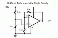
The gain is 2 so the voltage out will become 20 volts. Good idea but you forget the parameter "power supply rejection ratio", PSRR. At higher frequencies noise will go via pin 7, into the opamp and out at the output.
The super regulator concept will have extremely good PSRR = clean voltage when the input voltage is not so clean.
The super regulator concept will have extremely good PSRR = clean voltage when the input voltage is not so clean.
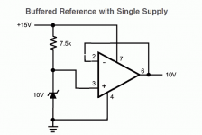
My mistake. I suppose then for unity gain something like the schematic attached. Or, for 10V output, use the original schematic with a 5V Zener.
Good point about the PSRR, I admit the Jung circuit solves this in a very neat way, powering the error amp from the regulated output. However, is the ripple rejection performance of a decent opamp significantly worse than the LM317/337? At 100kHz, the PSRR of some op-amps I looked was about 30dB (perhaps worse here since this circuit doesnt use a split supply?), while the 3 terminal regs varied from 10-40dB depending on if negative/positive or if the adj. cap was used.
If I could get the same noise performance, the the op-amp solution would still be worth looking at since the dynamic performance should be better, no?
/R
Attachments
You just have to compare the datasheets for the parts in mind. LM317 is pretty good as you will discover.
This is a good way to power low power circuits.
A thing to consider is that you will propbably will have some capacitance on the supply lines at the circuit to be powered. This must be supported by the opamp. That should not be a problem as long as you keep the cap high enough. A small resistor inside the feedback loop to limit the chargiung current at switch-on would be adviseable.
But, why not use a small-signal transistor as the pass transistor? That should not add more than a few cents to the price and you could retain all the advantages of the super reg, including feeding the opamp from the output voltage.
Jan Didden
The LM317 is excellent when implemented properly. I suggest you take another look.
Your design is flawed IMO as no matter how perfect your op-amp PSRR, you are relying on a Vref that is poor. I appreciate you say "that's easily dealt with" but you are hiding from us a fundamental part of the circuit.
Your design is flawed IMO as no matter how perfect your op-amp PSRR, you are relying on a Vref that is poor. I appreciate you say "that's easily dealt with" but you are hiding from us a fundamental part of the circuit.
TL431 or LM10 --
i built my first logarithmic amplifier with the LM10 (for use with photodiodes) -- it is a really nifty chip combining an error amplifier and reference with access to Vin+ and Vin-, Balance, etc. output impedance is rather high so must be used with an NPN or PNP transistor.
TL431 -- 2 TI engineers wrote an article in EDN on its use as an error amplifier and reference -- it was in an SMPS -- they discuss loop compensation in the article. http://www.edn.com/contents/images/091505di.pdf
I began this wondering if there was any useful middle ground between the Jung super reg. and the LM317. For a design to be worthwhile it must be considerably simpler than the Jung circuit, and considerably better than the LM317.
The super-reg is about two dozen parts. The LM317 is four.
So to with regards to Jan's suggestion that I use a small signal pass transistor: yes, I'm receptive to the idea, but can it be done without the trappings of the zener, the LED, all the extra passive components found in the super reg.?
Can we build a credible regulator from, say, 8 parts and $5?
-rjm
you can get a really good off-the-shelf regulator from Linear Tech or TI for less than $5 -- like the LT1763 or LT1964 -- at least 2 orders of magnitude "quieter" -- but it won't be a superreg -- and it won't have the super-reg's problems (it can oscillate, sometimes it fails to "start")/
most of your budget will be consumed by the error amplifier -- the AD825ar or AD817 --
most of your budget will be consumed by the error amplifier -- the AD825ar or AD817 --
rjm said:
***
Can we build a credible regulator from, say, 8 parts and $5?
-rjm
I agree with jackinnj, the Linear Technologies regulators have superior specifications, at least as to noise, i've been using those tiny surface mount devices for over a year in various projects like for the buffer/driver in my
Gainclone. Circuit is on that page or here, but it is very similar to the LM317 circ in terms of the parts to use.
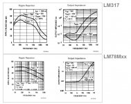
I've been comparing the datasheets (always a bad idea...) of the LM340 (LM78Mxx) and LM317. The output impedance and ripple rejection curves vs. frequency are, with Cadj on the LM317 omitted, essentially the same.
So is the main performance advantage of the LM317 simply due to its optional bypass cap, or is there something I'm missing?
-rjm
So is the main performance advantage of the LM317 simply due to its optional bypass cap, or is there something I'm missing?
-rjm
Attachments
btw, i found that the LTC low noise regulators behaved better with tantalums than aluminum electrolytics -- could just have been my layout.lgreen said:
I agree with jackinnj, the Linear Technologies regulators have superior specifications, at least as to noise, i've been using those tiny surface mount devices for over a year in various projects like for the buffer/driver in my
Gainclone. Circuit is on that page or here, but it is very similar to the LM317 circ in terms of the parts to use.
Adding 10uF as Cadj improves the LM317 response dramatically.
Yes, yes... but is that all there is to it, Cadj?
Or could it be that its not the ripple rejection, but the intrinsic output noise that's important?
/R
Pretty much just Cadj. The noise level of the 317 is lower than the 78 series, so IMO using it and adding Cadj are no brainers.
rjm said:[snip]The super-reg is about two dozen parts. The LM317 is four.
So to with regards to Jan's suggestion that I use a small signal pass transistor: yes, I'm receptive to the idea, but can it be done without the trappings of the zener, the LED, all the extra passive components found in the super reg.?
Can we build a credible regulator from, say, 8 parts and $5?
-rjm
rjm,
This being DIY, I am little surprised that the # of parts (cheap ones at that) is so important to you. Maybe you want to limit board area, I can also understand that. But, what you could do is to use an integrated current source diode or a suitable jfet current source instead of the LED and transistor current source. That is only one part, but it might be as expensive as the LEd etc.
Jan Didden
Jan,
I'm interested in providing separate regulation for each op-amp, which necessitates a total of eight units. Board area is, if I keep them on the main PCB, extremely limited... although a daughterboard is an option.
I could of course drop the condition of individual regulation, and its an open question whether two Superregs beats eight 3-terminal ICs. However, for the purposes of this thread, I wanted to restrict the discussion to solutions which were not too much more complicated than an LM317. i.e. an opamp and voltage reference, for example, possibly with a pass transistor... just to see if anything useful along those lines presented itself.
I am, as you might guess, now thinking I should just stick with the LM317...
/Richard
I think noone can tell you the right answer, you'll have to test this by yourself. 🙂rjm said:I could of course drop the condition of individual regulation, and its an open question whether two Superregs beats eight 3-terminal ICs.
- Status
- Not open for further replies.
- Home
- Amplifiers
- Power Supplies
- Simple Low Power Voltage Regulator