AndrewT said:Hi,
re isolated PSUs per channel.
Can 4 secondaries, one pair feeding each bridge rectifier achieve this?
If one pair of secondaries feed paralleled bridge rectifiers supplying the two channels, can isolation be achieved? I think not.
The diag I have drawn has galvanically isolated PSU's. IOW a
separate transformer for each channel.
You guys all talk about many grounds but no one talks about
-current loops-.
This is the important thing.
Cheers,
Terry
My guess is 25-30mv drop on emitter
Then touch cooling and it should be medium hot and nice to touch
Then you can make small adjustments on one channel, and listening to music you should be able to hear which channel is better
Actually the right bias is an exact value where it is most stable
Then touch cooling and it should be medium hot and nice to touch
Then you can make small adjustments on one channel, and listening to music you should be able to hear which channel is better
Actually the right bias is an exact value where it is most stable
Hi Kle,
what's Amp guru's recomendation for smoothing caps for the GB300?
Sorry if that sounds like a put down but one pair on each channel does not seem to fit.
what's Amp guru's recomendation for smoothing caps for the GB300?
Sorry if that sounds like a put down but one pair on each channel does not seem to fit.
KLe said:This amp was a Metaxas Solitare
You should be hanged for that, but it looks smashing.
The constructional layout of the Solitaire is still unbeaten imo.
Mr Ball will be pleased that you "simple killered" the 4 big Golden Roederstein caps, not sure what he'll think about the 1,6 KVA transformer

Hi AndrewTAndrewT said:Hi Kle,
what's Amp guru's recomendation for smoothing caps for the GB300?
Sorry if that sounds like a put down but one pair on each channel does not seem to fit.
put down ... no, not at all


 hehehe
Actually, I think Greg would like see 30KuF/rail (minimum). This one has 20KuF/rail, but, it is still sounds excellent

Unfortunately the Metaxas self-destructed, so now, it has been re-born into a stable and highly tunefull musical instrument
 excellent

jacco vermeulen said:You should be hanged for that, but it looks smashing.
The constructional layout of the Solitaire is still unbeaten imo.
Mr Ball will be pleased that you "simple killered" the 4 big Golden Roederstein caps, not sure what he'll think about the 1,6 KVA transformer
Hi jacco vermeulen
Worry not, the re-birth has been well worth the effort

 As good as the Solitare was, the GB300D is better, most definitely
Sorry, the Roederstein caps self-destructed and leaked all over the boards, which likewise self-destructed, so, the PS caps are now BHC aero's

Kle,
looks like the chassis was made for the 300GB boards.
What a pity the fantastic NEC devices of the Solitaire got wasted.
What is the 300GB Costas like compared to the Solitaire ?
looks like the chassis was made for the 300GB boards.
What a pity the fantastic NEC devices of the Solitaire got wasted.
What is the 300GB Costas like compared to the Solitaire ?
Hi jacco vermeulen
Yes absolutely, the 300GB boards fit the chassis perfectly. Very nice, indeed.
Yes absolutely, the 300GB boards fit the chassis perfectly. Very nice, indeed.
Hi msamkl
The Metaxas GB300D has absolutely no hum/noise. Its as quite as a mouse. (closest one I could find to a mouse)
So, maybe your should email Greg about how this one was constructed. Just an idea
Hope this is helpful
The Metaxas GB300D has absolutely no hum/noise. Its as quite as a mouse.
(closest one I could find to a mouse) So, maybe your should email Greg about how this one was constructed. Just an idea
Hope this is helpful
MODS FOR ska
heY everyone, I'm in the process of putting my SKA's together, I am still awaiting for parts and sourcing a enclosure.
DOes anyone have updates on the mods shinObiwan and MAcka?
I want to implement the mods myself just wanted to know how everything is sounding.
This is my first amp build and I am no way an EE but this site and others have been very helpful, Gregg himself is such a great guy and has any question that I 've had for him!
BTW, what is every one using with their SKA'a
Thanks Everyone!
KLe said:Hi msamkl
The Metaxas GB300D has absolutely no hum/noise. Its as quite as a mouse.
So, maybe your should email Greg about how this one was constructed. Just an idea
Hope this is helpful
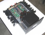
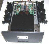
Thanks KLe, maybe ShinObiwan and Macka could help me if they were able to send me their Grounding schema. I'm in constant contact with Greg and he's making any effort to help me out with this. Here is a picture of my Amp's inside...
Thanasis.
Attachments
msamkl said:
Thanks KLe, maybe ShinObiwan and Macka could help me if they were able to send me their Grounding schema. I'm in constant contact with Greg and he's making any effort to help me out with this. Here is a picture of my Amp's inside...
Thanasis.
Guys,
Which ground scheme did Greg end up recommending.
Cheers,
Terry
Hi msamkl,
I, too, have an SKA with no grounding problems. After trying a couple of different approaches I implemented the designers grounding scheme exactly as he suggested. You can see from the spectrum that I posted earlier that all supply artifacts are 100 dB or more down. My system uses a single transformer and a single supply, so it may be a bit easier.
Did you use two conductor shielded input wiring or single shielded input wires? Do you have both ends of the input shield connected?
Bill
Hi Msamkl,
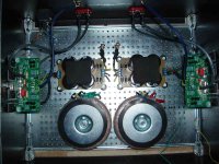
just a thought when looking at your pic of the perforated baseplate.
When wiring up mains supply from a metal distribution board enclosure, it is absolutely imperative that all the cables (L+N+E) coming from the mains incomer pass through the same hole and similarly all the cables feeding out pass through the same hole.
You have effectively put flow and return through different holes for every supply coming into and out of the transformers.
Has this anything to do with the hum?
Have you double insulated each cable (cord) as it passes through the perforations or at least put grommets around them? Particularly the mains input which should be double insulated and grommetted.
wwood said:Hi msamkl,
I, too, have an SKA with no grounding problems. After trying a couple of different approaches I implemented the designers grounding scheme exactly as he suggested. You can see from the spectrum that I posted earlier that all supply artifacts are 100 dB or more down. My system uses a single transformer and a single supply, so it may be a bit easier.
Did you use two conductor shielded input wiring or single shielded input wires? Do you have both ends of the input shield connected?
Bill
Guys,
Disregard my wiring layout on post #97. It was based on msamkl's
two diagrams on posts #95 and #96. They are wrongly
representative of the boards grounding. Looking at these diag's
I assumed that SKA had only 1 ground on the board and based
my solution on that.
I just saw the original diagram on post 1 by macka and it is obvious
from this diagram that the grounds are split on the board and
separated by some R, probably 10 ohms. It would have been nice
if someone had mentioned this.
Too busy to take in -all- the details of the thread.
Cheers,
Terry
Hi TerryTerry Demol said:Guys,
Disregard my wiring layout on post #97. It was based on msamkl's
two diagrams on posts #95 and #96. They are wrongly
representative of the boards grounding. Looking at these diag's
I assumed that SKA had only 1 ground on the board and based
my solution on that.
I just saw the original diagram on post 1 by macka and it is obvious
from this diagram that the grounds are split on the board and
separated by some R, probably 10 ohms. It would have been nice
if someone had mentioned this.
Too busy to take in -all- the details of the thread.
Cheers,
Terry
Sorry, I didn't notice 🙂
Greg built mine and I have just enjoying the music, but, yes you are right 😎
Input gnd is 10R to PS gnd and Speaker gnd is direct to PS gnd.
- Status
- Not open for further replies.
- Home
- Amplifiers
- Solid State
- Simple Killer Amp Constructor Thread