Having problems with my 300W kits 🙁
well i was finish 2 300Watts kits, but cant get it working,
Greb says this in the manual
2. Switch on and slowly increase the trim-pot VR1 (rotate anti-clockwise looking from the centre) until 1.5V is across the 10R resistors and holding stable. This will rise as the thermal loop is
established.
well i never get 1.5v, one kit give me 0.5v when i measuere each resitor, and the other give me 0.8v
someone know what i do wrong ? 😀
i ****** up something for sure hehe
Hi,
Ampguru (Greg) is on holiday at the moment.
He offers full support by Email as well as continuous use of www.diyhifi.org under sponsored threads.
Go there and use his excellent support.
Ampguru (Greg) is on holiday at the moment.
He offers full support by Email as well as continuous use of www.diyhifi.org under sponsored threads.
Go there and use his excellent support.
Hi Sam,
does the Ibias adjustment turn the current down to zero?
What DC voltage have you got from the supply?
Hi all,
what are the resistor numbers that define the constant current from the sources?
Do these resistors have the same correction applied as in the GB150?
does the Ibias adjustment turn the current down to zero?
What DC voltage have you got from the supply?
Hi all,
what are the resistor numbers that define the constant current from the sources?
Do these resistors have the same correction applied as in the GB150?
Yes, the Current is Zero if turn the VR1.
The DC that i have are 51V
R10 and R12 are the resistors, i added in parallel an 22K resistor, but still without reach the1.5V, now using 10K and i reach it! but the voltaje are variable, from 1.4 to 1.7 , is that ok?
The DC that i have are 51V
R10 and R12 are the resistors, i added in parallel an 22K resistor, but still without reach the1.5V, now using 10K and i reach it! but the voltaje are variable, from 1.4 to 1.7 , is that ok?
Hi Sam,
in the absence of Ampguru, here goes.
The CCS and the drivers take less current when the supply rails are low. These control the output bias current.
Your +-51Vdc is low by gb300 standard.
If your gb300 operates like gb150 then increasing the CCS current allows a bigger bias voltage/current to be reached.
Your //10k mod seems to confirm this.
You appear to have done the right thing reducing the CCS resistors by adding the //10k.
If you increase the supply rail voltage you MUST reduce the CCS current before connecting up. You may have to undo the //resistor change to get back to a nice adjustment range.
The gb150 bias current wanders slightly. This hunting is reduced by close coupling the temperature sensors to the output heatsink. The drilled hole option and filled with heatsink compound, seems to minimise the hunting but does not eliminate it.
The kit works 🙂
cant beliave it... now, how can i measure if the sound is ok? i compared it with my Old Yamaha Amplifier and i think that the yamaha have a little more dynamic sound, is that possible?
I will try to finish the other kit to build the 2 channels amplifier this weekend.
The first problem to check the sound are my drivers (B&W 602) these are rated 120W. but is ok, coz i have an pre-mixer, so i set the main to 50% and play with the channel gain.
I really want to see some technical diferences between my Yahama and the Gregs Kits, is possible to do that? i just have an Oscilloscope and Multimeter 🙂
btw, im really happy, and i think that after a few days playing music the amplifier will works better and better.....
Another question is... wich is the normal temperature that my transistors can works? i wanna test it at full power, using my temperature probe of my multimeter.
well, i have too many questions, but im very happy!!!!!!
really cant beliave it.
Hi,
Ampguru warns against continuous high power use, including PA use, for these domestic amplifiers.
Sinewave testing is very stressful, particularly if you test into a reactive load.
YOU MUST KEEP THE HEATSINK COOL.
Otherwise you risk blowing up the output stage and taking out drivers and maybe a whole lot else.
Arrange for a toggle switch to increase the test signal from -30db to -10db and very quickly gather test data.
Immediately switch back down to -30db.
Allow time for everything to cool.
Take the test level upto -28db and repeat the +20db switch of the signal, which should last for no more than 3 to 4 seconds, allowing time for cooling between each run. Gradually move towards -18db & +2db to see what happens at clipping level.
Be it on your own head when it blows up due to high heatsink temperatures.
I find my gb150 runs at 15Cdegrees above ambient and Ampguru approved that in my temperate climate. If you have high summer temperatures you should consider a lower differential above ambient temperature. He recommends big sinks and has recently re-issued heatsink info suggesting even bigger.
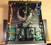
My case is really small i think 🙁 hope this dont give me noise problems, here is an pic of how i think that will put it in the case.
An externally hosted image should be here but it was not working when we last tested it.
The 2nd Kit dont work :S show me 0V in the resitors 🙁
and if i measure the PSU with the kit connected show me in V+ like 80v and v- show me 4v.
and if i measure the PSU with the kit connected show me in V+ like 80v and v- show me 4v.
Hi Cliff,
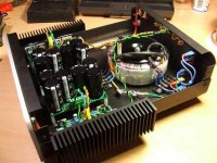
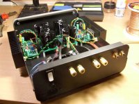
I just realised you are using an ATI case.
I tried to fit the sink internally and gave up the idea of stereo in that size of case.
Again, well done.
I notice ONE disconnecting network from safety to audio ground.
Will that work with a two channel amp?
How do you avoid a hum loop?
You WILL use a light bulb for the first power up!!
AndrewT said:Hi Cliff,
I just realised you are using an ATI case.
I tried to fit the sink internally and gave up the idea of stereo in that size of case.
Again, well done.
I notice ONE disconnecting network from safety to audio ground.
Will that work with a two channel amp?
How do you avoid a hum loop?
You WILL use a light bulb for the first power up!!
The sinks (Fischer) will work OK like that. I tried a mockup, case closed, with 25W per side on power resistors. No problem at all.
I guess the whole case is a heatsink, as well!
Since I mostly listen to very dynamic (chamber) music I don't expect to run them at anywhere near their max power.
Only one ground lift is needed, I assure you. I'll post the 'scope traces . 🙂 [Edited] If only one Xfo is used there can only be one network, otherwise they will both just be in parallel
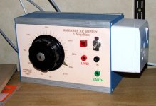
I prefer to use a Variac which I made many years ago. Check everything sequencially and wind it up very slowly. I also use a good old fashioned AVO in current mode in series.
On the 1 amp AC range its ballistic trip makes a very good cut-out.
Attachments
Hi Cliff,
if separate disconnecting networks go to the audio grounds for each channel, then the audio grounds go to the RCAs, then the RCAs go to the source equipment that almost certainly have a common RCA ground, the loop is avoided.
I really do ask "how do YOU avoid a hum loop"? I want to copy it!
if separate disconnecting networks go to the audio grounds for each channel, then the audio grounds go to the RCAs, then the RCAs go to the source equipment that almost certainly have a common RCA ground, the loop is avoided.
I really do ask "how do YOU avoid a hum loop"? I want to copy it!
I think you misunderstand:
The diode/R network is between the Xformer common and chassis safety ground.
How can you have more than one network if there is only one transformer?
The diode/R network is between the Xformer common and chassis safety ground.
How can you have more than one network if there is only one transformer?
well, im ****** up the kit dont work... will unsolder all the components and will sold it again 🙁
- Status
- Not open for further replies.
- Home
- Amplifiers
- Solid State
- Simple Killer Amp Constructor Thread