Hi folks
I've just built this circuit on veroboard but using BF256B and BC527-25 as substitutes. This is for a headphone amplifier, and I haven't fired it up to test yet.
Do I need to change any resistor values to account for the different transistors?
I have a pair of 15v linear regulated supplies I have built going spare, can I run this circuit at 15v instead of 12?
Attachments
Last edited:
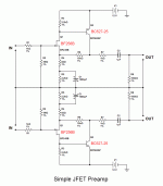
Use a MOSFET for the output and give it about 70mA to 120mA bias current and use a 2200uF output cap and it becomes a pretty powerful headphone amp.
Like this:
Like this:
Thanks for the advice guys, much appreciated.
Why won't it drive headphones? Not enough gain or not putting out enough current? Sorry for the newbie questions, but this is my first diy amp attempt.
That pocket class A looks good,nice and simple, I'll build that to use instead, the circuit I already build will come in handy as a preamp stage in other projects so no loss.
I have some BF862s I can use, I soldered them to adapter PCBs
I don't have any ZVN4306 though, can I substitute one of the MOSFETs I already have, which are:
PHT4NQ10LT (SOT-89, soldered to adapter board)
IRF640 TO-220
Do I need to match the JFETs and MOSFETs as pairs to get good soung quality with this design?
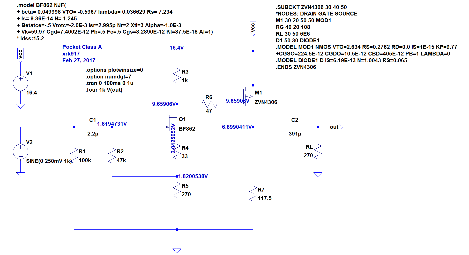
A few questions about that circuit, is V2 the input?
I don't have any 2.2uF caps to hand but do have a large pile of 1uf and 0.22uF MKT polyester caps, could I parallel two of the 1uF and one of the 0.22uF to make a 2.22uF array instead of buying some 2.2uF caps?
C2 - closest values I have are 330uF and 470uF, would either of those do instead of the 391uF on the diagram?
VCC of 16.4V, does this have to be precise? Can I use an 18V supply using a 7818 reg as I already have two such supplies I built?
A few questions about that circuit, is V2 the input?
I don't have any 2.2uF caps to hand but do have a large pile of 1uf and 0.22uF MKT polyester caps, could I parallel two of the 1uF and one of the 0.22uF to make a 2.22uF array instead of buying some 2.2uF caps?
C2 - closest values I have are 330uF and 470uF, would either of those do instead of the 391uF on the diagram?
VCC of 16.4V, does this have to be precise? Can I use an 18V supply using a 7818 reg as I already have two such supplies I built?
Parallel caps is fine, anything from 330uF to 2200uF works for output. Lower impedance phones need bigger caps. 250ohms cans only need 470uF caps. 18v supply is fine. Any n channel mosfet works. IRF610 etc. 18v is perfect - the simulation was 16.4v as that’s what two 9v Li-ion batteries make.
In that thread there is the desktop version - which sounds more like what you are making:
The schematic has lots of input and output cap options so looks complicated. Same circuit but with IRF610 and 125mA of bias current.
Last edited:
Excellent, cheers. The desktop version differs in that it's intended to run off a PSU rather than batteries?
I reckon I have the needed parts, the IRF640s are not ideal, according to what I have read, something about them having too high transconductance and therefore poor response to the higher frequencies, but I have 15 of them I got really cheap, and I recon they will suffice for this project.
As to what I'm building, my thoughts were simply, hmm, let's build an amplifier to learn how such things work, and I figured start simple with a simple circuit to drive a pair of headphones then I can learn the necessary skills to go on to larger and more powerful beasts.
So it's a learning exercise more than anything as I have a lot to learn!
Yes, a great beginner project as it is as simple as an amp gets. It sounds surprisingly good though and has been given some nice reviews.
XRK Audio NHB Pocket Amp Review - Headfonics.com
XRK Audio NHB Portable Class A | Reviews | Headphone Reviews and Discussion - Head-Fi.org
For desktop version you can use a wall wart Class 2 transformer to provide 24vdc and the cap multiplier drops it 4v down to circa 20v. Or you can use your 7818 etc regulator as you mentioned. That’s fine as well.
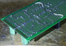
I've built the circuit, apart from two components I didn't have the right values, so I've ordered some.
I'll post pics tomorrow.
I'll post pics tomorrow.
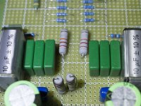
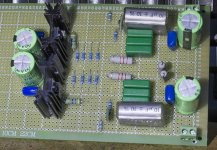
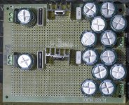
Here's how I built it, I have written in red the components I used, with the one out of spec part - the 1.2k resistor, in gold. I have outlined the missing two components in yellow and the input-output sections that I have thus far omitted in gold. I'll probably built the input & output parts on small boards and connect them to the amp board by wires.

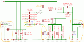
You can use 1/4w even 1/8w resistors everywhere except the four 270R loads in parallel below the MOSFET. Those should be 1W each minimum or a single 68ohm at 5W They are dissipating 1.25watts. So there are many places where you have oversized resistors except where it counts. Otherwise looks good.
Just use two of your 1uF dipped polyesters in place of the missing 10uF cap. And use one of your 270Ohm resistors in place of the 250Ohm resistor below the JFET - close enough and add maybe 4k7 in parallel to 270Ohm to get closer to 250ohms.
Also, if you are now going with the DCA, maybe post questions in that thread as more people may be able to help you and your questions will be helpful to others as well. Your call though as this is your thread.
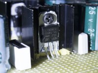
This image will help you in picking your parts to be similar in size and ratings:
Just use two of your 1uF dipped polyesters in place of the missing 10uF cap. And use one of your 270Ohm resistors in place of the 250Ohm resistor below the JFET - close enough and add maybe 4k7 in parallel to 270Ohm to get closer to 250ohms.
Also, if you are now going with the DCA, maybe post questions in that thread as more people may be able to help you and your questions will be helpful to others as well. Your call though as this is your thread.
This image will help you in picking your parts to be similar in size and ratings:
Last edited:
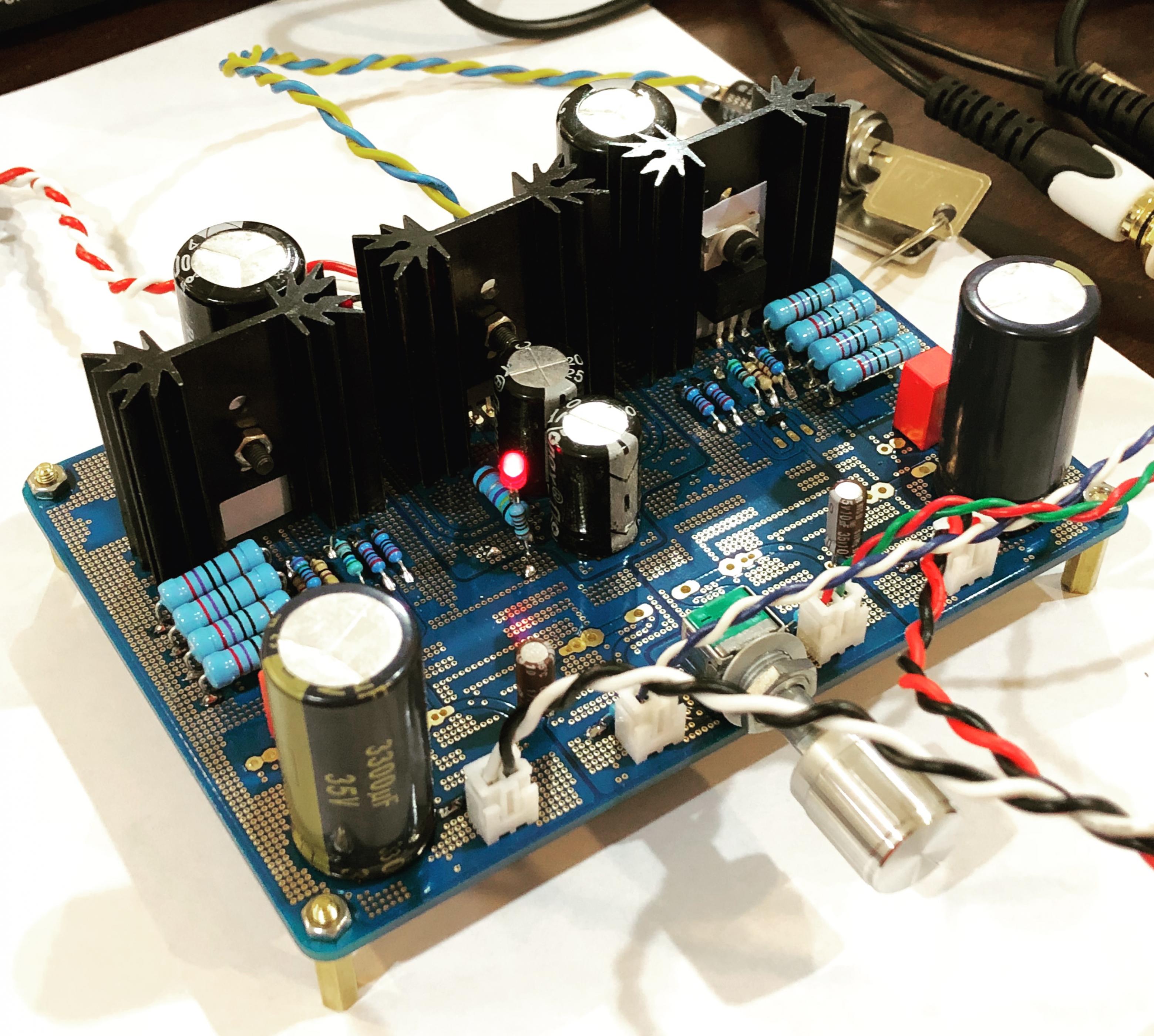
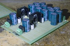
Thanks for the tips. Here are pics of what I've built.
The oversized resistors were because I just happened to only have those values in larger sizes.
Sadly, the four 270R resistors are either 0.25W Vishay or 0.6W Neohm, I forget, so I'll have to replace those with 1W types.
I shall indeed post in the DCA thread,, good tip, cheers.
The oversized resistors were because I just happened to only have those values in larger sizes.
Sadly, the four 270R resistors are either 0.25W Vishay or 0.6W Neohm, I forget, so I'll have to replace those with 1W types.
I shall indeed post in the DCA thread,, good tip, cheers.
Attachments

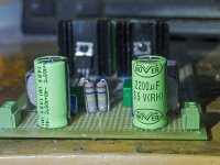
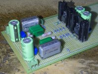
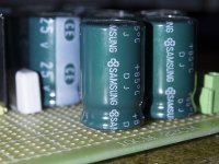
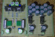
Here's some pics of the dual 18v supplies to power it.
Nothing fancy, just 7818 regulators using the circuit in the datasheet with a pair of polyproylene caps either side of the reg, I added the 2200uF Samsung caps for smoothing.
Nothing fancy, just 7818 regulators using the circuit in the datasheet with a pair of polyproylene caps either side of the reg, I added the 2200uF Samsung caps for smoothing.
Attachments
Last edited:
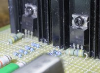
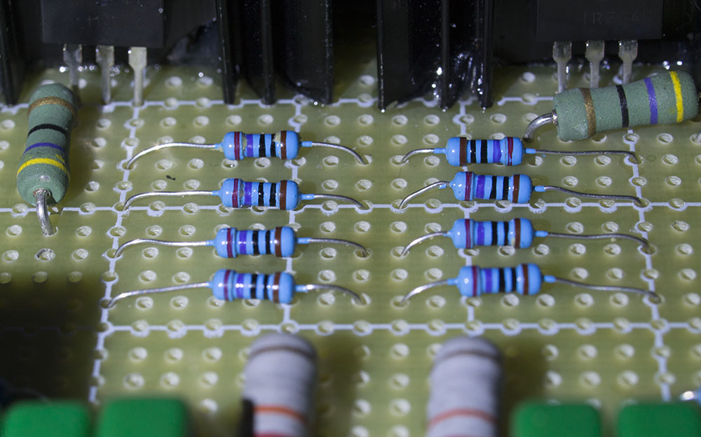
Here are the 270R resistors that I need to replace with higher wattage types, luckily the way I laid them out, there is plenty of room for bigger resistors to fit:
Very nice neat work, Ian Greenhalgh! If you ever decide to want a compact version, I have PCBs available that has the PSU on board (it is a cap multiplier) so a 24v wall war or SMPS is dropped to 20v - no voltage regulators (voltage stability not critical, but low ripple is).
Cheers,
X
Cheers,
X
Thanks very much for the help and advice. I'll definitely look at your PCBS when I have spare funds available, I blew my budget on lots of components, mostly transistors and caps...
I just went through my big box of resistors an the closest to 270R 1W I have is 220R 2W, would these be close enough in value to replace the 0.25W ones I soldered onto the board?
It will work temporarily. The bias current will be higher and midpoint voltage above resistor may be a bit off. But it will sound fine as long as you don’t drive to clip as it is asymmetric now. You want DC voltage after MOSFET and above resistor to be 1/2 Vcc. Adj 1k1 resistor to rebalance to 1/2Vcc.
- Status
- Not open for further replies.
- Home
- Amplifiers
- Solid State
- Simple JFET Preamp