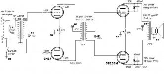
My 2A3pp is now running as a bread board and sounding very good. I have been showing it off to my friends and one of them has asked if I could design a cheaper version for him. I've had some thoughts and come up with the following design - it is built around various cheap components that we have access to. I would appreciate any comments, criticisms that you care to make.
ciao
James
ciao
James
Attachments
Why the Zeners?
Why not simply strap the 5B/255Ms as straight triodes? Zeners are noisy.
Ra as a triode would be about 2k so your 11k output transformer (100 mA surely?) would probably work quite well.
Do not worry about the g2 voltage limit when triode strapped. I have investigated this and so long as one does not go too far there will be no problem.
As an example, 6146 has a g2 limit of 250V. Philips gave details of triode operation at 400V. I have tested a 13E1 (g2 limit 300V) at 500V and 200mA with no problems.
7N7
Hi James
I've always liked your topologies and this one is no exception. What is the purpose of the 150ohm resistors in the plates of the input valves? At this level it should certainly make sense to use a better-sounding rectifier, possibly vaccum, mercury, TVdamper or at least some better silicon.
regards,
peter
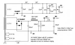
I would protect that first filter capacitor a little better... maybe just a 50 ohm resistor, or even better is to move the choke before the 200uF cap.
Joel
Joel
7N7
Many thanks for the feedback.
Zenars are noisy - except the 5V6 (or very close values) at this value the two dominant noise generating mechanisims produce about equal outputs and being random, they sum to half the noise level. Noise generation is close to a minimum for a zenar at this value too. I'll try it with a direct strap and with the zenars and see which sounds best.
I didn't know about the g2 limit applicability in triode mode. Thanks for the info. I'll try it at higher voltage and see how it goes.
The 10mA is for dc imbalance - sorry that's not clear from the drawing - I have found that pp dc balance is up to 10% away from best sounding ac balance so I always spec. my pp transformers with some dc current capability. The design hasn't got the pot in it to tweak this but I will build it both ways and see if this design is sensitive to tweaking this.
Peter,
Thank you for your comments.
The 150R resistors are a hang over from the 6C45 front end that I used in the 2A3pp. They may not be needed with the 6N6Ps but they made an audiable improvement with the 6C45. They are oscillation killers and the 6c45 seems to be a little rocket in that regard. I've never used the 6N6P before so I'm not sure they are needed, we'll see.
The silicon diodes are there to keep the B+ voltage up. I can get a power transformer to power both channels in this design for 51euros...but it only has a 270V high tension option... so silicon BR was required. I stick to 1N4007 as I've had plenty of practise putting snubbers on them and I can get them quite quiet....
For my 2A3s I'm thinking of using an 83 bridge and a 6D22s bridge and see which sounds better🙂
Too many options and not enough time to try them...
ciao
James
Hi Joel,
I need the first filter capacitor there to keep the B+ high. I could put a small resistor in front of it to limit surge current. I'll have a play with options and see what works best.
Thanks for the suggestion - it would be a very messy blowup!
James
I need the first filter capacitor there to keep the B+ high. I could put a small resistor in front of it to limit surge current. I'll have a play with options and see what works best.
Thanks for the suggestion - it would be a very messy blowup!
James
You could always put the 166uf up front and use a 33uf Solen for the third - you'd still have plenty of filtering. Why no dc on the heaters? It's cheap and will prevent possible headaches come build time.
Hi Pedroskova,
I could put the 166Uf at the front and keep the same voltage but I find that very low ripple (less than 50uV on line stage) and a big polypropylene at the end of the psu means that I get a much better sound. Infact my experiments with regulated psu versus this style of passive is showing the passive to be better for pp amps
No dc on the heaters because I don't like the sound of dc on the heaters... Good layout means I don't need dc on the heaters... That means three dimensional design to really get induced hum down. I also use all wooden chassis...don't like the sound of metal chassis. This also saves costs🙂 How many people find that their breadboards sound better than their final built version?
Thanks for your comments.
ciao
James
James D. said:
No dc on the heaters because I don't like the sound of dc on the heaters... Good layout means I don't need dc on the heaters... That means three dimensional design to really get induced hum down. I also use all wooden chassis...don't like the sound of metal chassis. This also saves costs🙂 How many people find that their breadboards sound better than their final built version?
oops, I thought your buddies would be building it themselves.
...wood chassis...

oops, I thought your buddies would be building it themselves.
Your right they will... but under my instruction as they are not experienced with tubes but are used to sand based equipment - they don't know what they are getting into 🙂
There was a lot of mickey taking going on until they heard my systems... They thought they were proper engineers until they met me... now they know that they are proper engineers....but the world isn't a proper world

ciao
James
Hi James,
I was just wondering whether you've found any measurable differences between using the zener/cap stack and a simple resistor betweem the plate and g2 on the 807's? And what are the audible differences?
I'm all out of zeners here (and <i>all</i> my parts are mail ordered) so I'll try this set-up on my little EL84 triode PP amps when I put in the next order. This technique is something I've known about for some time, but have yet to try.
Hi Brett,
I haven't measured this difference. I will when I get a chance...
When I tried it I prefered the zenar connection - it was cleaner sounding and nice and relaxed. It was also faster when required to be. These are characteristics I associate with very low distortion - so I guess it should measure better too. The difference was as I expected so I didn't bother to measure it...
I have been told that this is most effective for tetrodes and pentodes that were not designed for triode operation - so maybe there is less difference for EL84s,34s or I guess 807s....
ciao
James
Your design looks great for 5B/255M what input transformer other than Lundahl is there , maybe a Jensen ?
i have made one amplifier similar input splitter hammond 560Q 10K/10K driver transformer hammond 124F 15K:15K sound very nice with 6SN7 nos and 6C4C some people think hammond its not good, only they do not now how use thems and do not now witch one can do the job but i tell you these are very good transformers very well built long lasting and price its not high
Attachments
- Status
- Not open for further replies.
- Home
- Amplifiers
- Tubes / Valves
- Simple IT PP