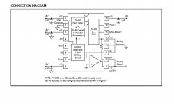
It's got it's own internal opamp I/V. attached.
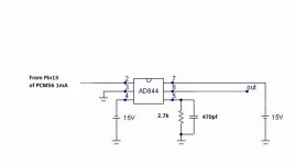
But if you want just current output, take it from pin13 1mA to an external I/V such as the AD844 with it's own buffered output. in this thread.
http://www.diyaudio.com/forums/digital-source/227677-using-ad844-i-v.html
Cheers George
But if you want just current output, take it from pin13 1mA to an external I/V such as the AD844 with it's own buffered output. in this thread.
http://www.diyaudio.com/forums/digital-source/227677-using-ad844-i-v.html
Cheers George
Attachments
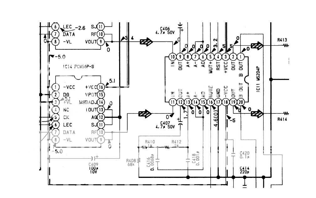
In the schematic the PCM56 are configured to use their internal opamps so technically this is not an I/V stage. This is an output stage. You can remove M5204AP by desoldering them. You will need to connect an output filtering stage connected to pin 10 and 11 though if you don't want it to be silent.
As georgehifi said you can skip the opamps with these DAC chips and use their current outputs but it will be some work. Current output can be superior with the right I/V circuits.
Passive output has its merits too.
As georgehifi said you can skip the opamps with these DAC chips and use their current outputs but it will be some work. Current output can be superior with the right I/V circuits.
Passive output has its merits too.
Last edited:
Thanks guys ! Both answers are quite useful for me , but probably i will go , with the :
I will remove the Mitsubishi's op amp and take the signal from there , Jean do you have a simple scheme for output filtering ?
In the schematic the PCM56 are configured to use their internal opamps so technically this is not an I/V stage. This is an output stage. You can remove M5204AP by desoldering them. You will need to connect an output filtering stage connected to pin 10 and 11 though if you don't want it to be silent.
I will remove the Mitsubishi's op amp and take the signal from there , Jean do you have a simple scheme for output filtering ?
Pin 9 and 10 connected you mean ? You can't use that output without any filtering ! You must do some filtering or you'll be disappointed. Sound will be bad plus your tweeters won't be glad.
Are you going OS or non OS ?
Some members were busy with PCM56 too in the past:
http://www.diyaudio.com/forums/digi...a7210-pcm56-dutch-american-connection-27.html
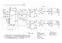
BTW an oldie, it is a non OS separate DAC with glue logic, a better opamp for I/V + active filter. Please note that 2 x 47 Ohm resistors are needed after the last opamps in series to the outputs.
Are you going OS or non OS ?
Some members were busy with PCM56 too in the past:
http://www.diyaudio.com/forums/digi...a7210-pcm56-dutch-american-connection-27.html
BTW an oldie, it is a non OS separate DAC with glue logic, a better opamp for I/V + active filter. Please note that 2 x 47 Ohm resistors are needed after the last opamps in series to the outputs.
Attachments
Last edited:
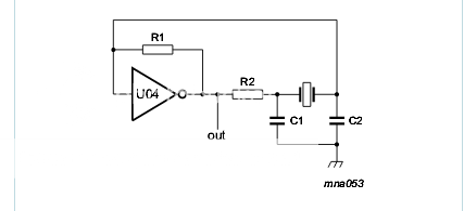
This is far simpler and with no global feedback to all users sounds better, as VHF glitches from the dac don't excite it. And there is a LP filter off pin 5 to ground. Pin 6 is to the output rca's. And it can be direct coupled if you use pins 1 and 8 dc offset nulling pot.
Cheers George
Cheers George
Attachments
Last edited:
Many moons ago I whacked up a discrete I/V converter with OP275 output filters and it sounded Much better than the stock circuit with the internal amps, and it never left the breadboard. Just putting that out there if you are expecting better sound available from the current output of this chip.
OP amp removed , player sounds completly different ! Open mids , fine highs bass is a bit relaxed . Now it might sound stuped , but have in mind i`m not an engineer , how to put this player Digital Filter to 4x oversampling or even NOS ? Filter used is ; CXD 2550p
An externally hosted image should be here but it was not working when we last tested it.
If you do not know exactly what you are doing then I recommend that you not attempt to convert this to NOS. It would likely require significant hacking of the PCB and existing circuit, which may render your DAC as completely non-working. However, Jean-Paul shows one possible PCM56 NOS implementation in post #6.
Ken , i will take the riskWhat i`m going to loose anyway
Um, yes, I recognize that you currently have a DF. My point is that you would need to bypass that DF chip somehow, which will almost certainly require hacking of the PCB. In addition, you would need to demux the data signal from the DIR chip, which is what some of the logic in post #6 does, producing stopped-clock operation.

- Status
- This old topic is closed. If you want to reopen this topic, contact a moderator using the "Report Post" button.
- Home
- Source & Line
- Digital Source
- Simple I/V bufeer for PCM56p