Hi ilorev,
In several projects I have added a jumper to select double triode pinout 9A (ECC82, ECC81, ECC83, 12AY7, 12BH7, 12DW7, etc...) or 9AJ (6N1P, 6N2P, ECC88, 6DJ8, 6922, etc...) 🙂
I am using the 6N1P or the ECC82, they are quite close except for heater because the 6N1P has a higher dissipation 🙁
You have two exemples attached...
Marc
Attachments
Hi Marc,
You DC protection board looks very neat. Can you share the schematic?
Thanks.
You DC protection board looks very neat. Can you share the schematic?
Thanks.
Hi,
I have started to build this amplifier but I sill need some components and I just send an order to Mouser 🙂
While I have done this work, I made some changes for several resistors values that I show in this new schema... For the output transistors the lateral MOSFET from Renesas that I am also using on the Amplifier made for music from Mooly are doing well and as soekris say you can get equivalent from Exicon, they are only a little bit more expensive 😡
The jumper selection for heater of the 6N1P can also be used to test other tubes like the 6FQ7 or 6CG7 ( https://s3.amazonaws.com/tubedepot-com-production/spree/attached_files/6cg7eh.pdf?1400185580 ). The ECC99 could be also interesting ( https://www.jj-electronic.com/images/stories/product/preamplifying_tubes/pdf/ecc99.pdf ) with the jumper on the ECC82 position.
For the SSR protection I forget the TVS protection, it is stupid because I have done it on an other DC protection
Rgds,
Marc

Hi flancfuster,
It is not my schematic, it has been done by Project16 post 54 and 58 here : Speaker Protection Using Optoisolator and I am not sure I can publish it, but you can contact him by PM 🙂
There is an other SSR DC protection very similar to the one I am using here : https://www.diyaudio.com/forums/att...sr-speaker-protection-mosfet-protect-v2-2-jpg In addition there is an over current feature...
I have made an other version with a UPC1237 device, but I didn't have the time to test it yet 🙁
Marc
Attachments
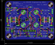
This is very interesting project, indeed!Now that I have finally received the PCB I will start to build and test them 🙂
Thank you Marc, looking forward to see your results on amplifier. I started to work on a layout from your schematics.
Note the interface SRPP/output .
...and the DC offset servo...
Best regards!


Hi flancfuster,
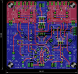
If you want to make your own PCB, I suggest you to use the version 5 HD which was modified with Hugh recommendations for the Mu-follower stage instead of the SRPP ! I didn't test it yet, but I had problem with the SRPP version 😡
Rgds,
Marc
If you want to make your own PCB, I suggest you to use the version 5 HD which was modified with Hugh recommendations for the Mu-follower stage instead of the SRPP ! I didn't test it yet, but I had problem with the SRPP version 😡
Rgds,
Marc
Attachments
Marc on the schematic attached, 0.1uF couling caps are missing. I can see only 0.22uF. Are they required?
Hi flancfuster,
If you want to make your own PCB, I suggest you to use the version 5 HD which was modified with Hugh recommendations for the Mu-follower stage instead of the SRPP ! I didn't test it yet, but I had problem with the SRPP version 😡
Rgds,
Marc
Last edited:
Nice amp, I have done also with that current source however that is a tube, and I have the mosfets dc coupled to the tubes, that is possible with a dc servo and a pauze into the speaker protection, I set it on 1 minute so tubes are warm before switch on. I did not use feedback and I am not a fan of mosfet relais between speaker.
DC coupled? I would like to try that. Can you share the schematic of your project?
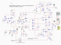
Here is a schematic of a all plate follower, this one dit sound so open that I was suprised, (without feedback) when use a higher mu preamp tube you need to connect feedback.
search on mine name here I have more somewhere, I am on a other pc now, programming so I can not send.
regards
Attachments
Thanks, I'm looking on other threads started by you. 🙂
Here is a schematic of a all plate follower, this one dit sound so open that I was suprised, (without feedback) when use a higher mu preamp tube you need to connect feedback.
search on mine name here I have more somewhere, I am on a other pc now, programming so I can not send.
regards
Hi,
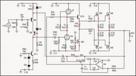
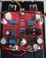
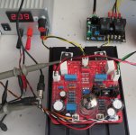
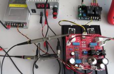
I am back with the Hybrid amplifier 🙂
I have made a lot of test with Rev. 5 and was never able to run correctly the MOSFET SRPP 😡 I have made a big mistake on the PCB because the 2SK1058 and 2SJ162 have a different pimout than other MOSFET : the middle pin and the flange is the source and not the drain !!! (https://www.renesas.com/us/en/doc/products/transistor/003/rej03g0847_2sj160ds.pdf & https://www.renesas.com/in/en/doc/products/transistor/003/rej03g0906_2sk1056ds.pdf)
Any way, after crossing the legs it still didn't play music, I found that there was no gain in the input stage 😕 After more test I finally gave up for some time...
Now I have decided to build the other version of the hybrid amplifier Rev. 5 HD, this is a version suggested by Hugh Dean which use a mu-follower stage made by Alan Kimmel instead of the SRPP. This time the input circuitry is working well and with about 1 V signal I have 10 V on C6 and C7 😀
Helas, when I put the power on the semiconductor part of the amplifier M1 (2SK1058) become immediately very hot (I burn my finger when I just touched it )
)
I don't understand what happen, I have only +30 V and -30 V, which is less than the 50 V specified and the 2SJ162 didn't become so hot ? Since the output stage is straightforward I don't see what can be wrong ? If you have some solution for this amplifier to play music, I will be happy...
Rgds,
Marc
I am back with the Hybrid amplifier 🙂
I have made a lot of test with Rev. 5 and was never able to run correctly the MOSFET SRPP 😡 I have made a big mistake on the PCB because the 2SK1058 and 2SJ162 have a different pimout than other MOSFET : the middle pin and the flange is the source and not the drain !!! (https://www.renesas.com/us/en/doc/products/transistor/003/rej03g0847_2sj160ds.pdf & https://www.renesas.com/in/en/doc/products/transistor/003/rej03g0906_2sk1056ds.pdf)
Any way, after crossing the legs it still didn't play music, I found that there was no gain in the input stage 😕 After more test I finally gave up for some time...
Now I have decided to build the other version of the hybrid amplifier Rev. 5 HD, this is a version suggested by Hugh Dean which use a mu-follower stage made by Alan Kimmel instead of the SRPP. This time the input circuitry is working well and with about 1 V signal I have 10 V on C6 and C7 😀
Helas, when I put the power on the semiconductor part of the amplifier M1 (2SK1058) become immediately very hot (I burn my finger when I just touched it
)I don't understand what happen, I have only +30 V and -30 V, which is less than the 50 V specified and the 2SJ162 didn't become so hot ? Since the output stage is straightforward I don't see what can be wrong ? If you have some solution for this amplifier to play music, I will be happy...
Rgds,
Marc
Attachments
-
 IGros plan ampli hybride rev 5 HD.JPG176.6 KB · Views: 617
 -
 Test ampli hybride rev 5 HD.JPG333.5 KB · Views: 578
 -
 Test 3 ampli hybride rev 5 HD.JPG.JPG202.6 KB · Views: 566
 -
 Test 2 ampli hybride rev 5 HD.JPG278.1 KB · Views: 267
 -
 PCB Hybrid amplifier Rev.5HD.png141 KB · Views: 266
 -
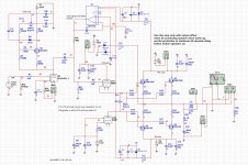
Schema Hybrid amplifier Rev.5HD.pdf141 KB · Views: 437
Be aware that lateral power mosfets have a large and unlinear input capacitance and to reduce high frequency distortion, they should therefore be driven by a low impedance source, I don't know the output impedance of the tube driver, but even the gate resistors are too large....
Good alternatives to the now unavailable Hitachi Lateral Power Mosfets parts are Exicon, available at Profusion.
The output mosfet relay are a good choice, but they should be protected, t.ex. by a TVS.
The gate protection zeners should also have a series diode, otherwise they conduct when you don't want them to.
That is why I did use a 6N6P platefollower loaded with a current source, with tubes dc coupled to gates.
regards
Attachments
- Home
- Amplifiers
- Tubes / Valves
- Simple Hybrid tube amplifier with MOSFET output