And what about Tom's Maida II regulator?
I used it, very good regulation, and low noise.
https://www.diyaudio.com/community/threads/21st-century-maida-regulator.209067/
I used it, very good regulation, and low noise.
https://www.diyaudio.com/community/threads/21st-century-maida-regulator.209067/
28V is dropped in the 560R resistor. OP needs another 30V drop? Increase 560R to 1k.kodabmx,
You suggested the TL783. Good idea.
But your schematic had 400V in and 350V out into a 50mA load. It claimed that the dissipation in the part was only 845mW. ?
A simple voltage dropping resistor has a dissipation of (400V - 350V) x 50mA. 50V x 0.05A = 2.5 Watts dissipation.
(But there is no regulation versus current changes, so do not use a dropping resistor).
Perhaps you meant that the TL783 only takes an additional 845mW to run the internal chip circuits; not including the 50V x 50mA = 2.5 Watts?
And, the OP request is for 430V to 350V (80V drop). 80V x 0.05A = 4.0 Watts.
I would sure use an adequate heat sink on the TL783.

I usually put the reg on the chassis. It needs a good insulating kit and the input resistor protects if there is short. I am not quite there with the exact regulated voltage around 350v for e88cc LTP driver (plate load 33k @ 230V) cathodes at 110V.
The TL783 looks easy and am not adding complexity where the audio signal does not pass through. The LM431 with the feedback including the device - I am not sure on stability without prototyping.
The E88CC k/f voltage is +120V maximum.
If for some reason the cathode quiescent voltage biases more than +120V, instead of +110V, you will need to elevate the E88CC filaments.
Your cathode is at +110V, if you have more than +20V grid signal swing (+10V swing on the cathodes), that is too much.
But that would require a +20V grid signal swing, so it probably will not happen.
@baudouin0 The only issue with TL783 is availability... Mouser won't have stock till July!
You can modify the design to use LM317 though. Use 1N5363 instead of 1N5378... I have a board made up for this regulator if you're interested. You can give it AC from the transformer directly 🙂 I spec HER208 because I also use this regulator with a 37kHz source.

You can modify the design to use LM317 though. Use 1N5363 instead of 1N5378... I have a board made up for this regulator if you're interested. You can give it AC from the transformer directly 🙂 I spec HER208 because I also use this regulator with a 37kHz source.
Last edited:
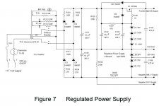
For the curious & others here is another simple SS regulated supply suitable for tube amps.
Just a single IFR840 connected as a Source follower, tied to a string of Zeners.
And it has -ve voltages for the 2-stage differential front end.
I like the KISS principle, the tube amp on its own has enough problems without the added
complexity of a complete regulated supply with its error amp & so on. 🙂
Attachments
https://www.eevblog.com/forum/projects/ccfl-inverter-as-basis-for-easy-low-current-500v-dc-supply/OK I gave this a go based on #8. Even simpler. Works in simulation but oscillated (a good sign of regulation)! Added C11 which seems to solve that. However, it is something I need to prototype.
View attachment 1103065
https://www.eevblog.com/forum/projects/tl431-common-base-amplifier-stability/
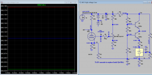
Based on the above here is is sim for even higher regulated voltage, the regulation is good. Is such sch acceptable or comparable to gas filled regulator. Added emiter resistor to Q6 improves stability as gain is reduced. I know temperature co-efficient for TL431 is about 5mV/K, any stability issue?
Attachments
Last edited:
- Home
- Amplifiers
- Tubes / Valves
- Simple HT voltage regulator